

 English
 русский
 Español
 عربى
عربى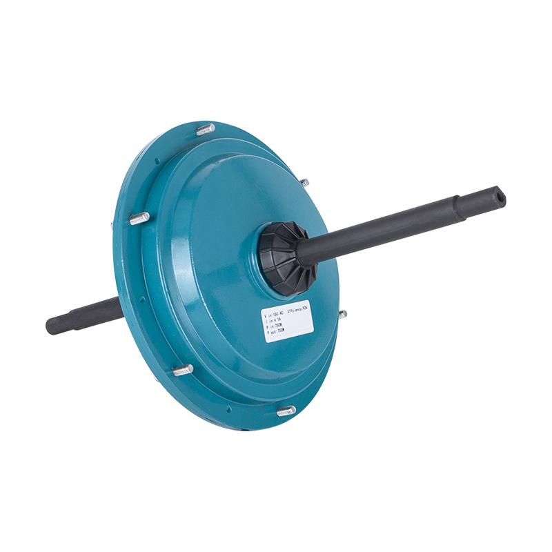

No. 8, Duxiu San Road, Ganlin Town, Shengzhou City, Shaoxing City, Zhejiang Province, China

News Category
Product Category
How to Connect BLDC Motor with Controller: A Complete Wiring and Setup Guide
Content
- 1 Understanding BLDC Motor and Controller Connections
- 2 Wire Identification and Standard Pinouts
- 3 Step-by-Step Wiring Sequence
- 4 Phase Order, Hall Phasing, and Direction
- 5 Electrical Ratings and Protection
- 6 Installation, Shielding, and Thermal Management
- 7 Safe Testing and Troubleshooting
- 8 Connecting BLDC Motors in Industrial Air Cooler Applications
- 9 Common Mistakes to Avoid
When a brushless DC (BLDC) motor arrives at your workbench or in a customer machine, the first question is almost always the same: how do I connect this motor to the controller without damaging either component? The answer is straightforward once you separate the few wires involved: three phase windings, five Hall sensor lines, and a DC power pair. If you get the phase order and Hall phasing right, the motor will run smoothly from the first spin. If you get them wrong, you will see noise, vibration, overheating, or no motion at all. This guide gives you the exact connection sequence you need, the reasons behind each step, and the safety checks that prevent a costly mistake in an industrial setting.
Understanding BLDC Motor and Controller Connections
Before you pick up a screwdriver or a soldering iron, it helps to understand why a BLDC motor is different from a standard three-phase induction motor. A BLDC motor has permanent magnets on the rotor, and the stator carries three phase coils. To make torque, the controller needs to know the rotor position at all times. Therefore, most industrial BLDC motors have internal Hall effect sensors that send a position signal back to the controller.
How a Brushless DC Motor Produces Torque
The controller switches current through the stator phases in a sequence that follows the rotor position. The phase currents create a rotating magnetic field that pulls the rotor's permanent magnets along. In a three-phase BLDC motor, the switching sequence is A-B-C or A-C-B, depending on whether you want clockwise or counterclockwise rotation. Because the switching is electronic, there are no brushes to wear out, which is why BLDC motors are used in applications that require long service life and predictable speed control.
Three Types of Feedback: Hall Sensors, Encoders, and Sensorless
Most industrial BLDC motors are equipped with Hall sensors on the stator. These sensors are usually rated at 5V and produce a commutation signal that tells the controller which phase pair needs to be energized next. Some high-end motors have encoders for precise position or speed feedback, but the connection scheme is different. Sensorless BLDC controllers estimate rotor position from back EMF, but they are more common in low-cost fan drives found in home appliances and small ventilation designs. For the purpose of this guide, when we talk about connecting a BLDC motor with a controller, we are primarily dealing with Hall-sensor motors, which are the standard for industrial air coolers, fans, and pumps.
What the Controller Must Deliver
A BLDC controller needs to take DC power from the supply, convert it into three-phase PWM waveforms, read the Hall sensor inputs, and provide a way to control speed and direction. It also needs a DC bus capacitor to smooth the voltage, a current sensing circuit to limit overload, and sometimes a braking or regeneration channel. When you connect the motor, you are essentially creating a closed loop between the controller output stage and the motor's Hall sensors. If any of these links are broken, the controller cannot commutate the motor correctly, and the motor will stall or run erratically.
Wire Identification and Standard Pinouts
Modern BLDC motors and controllers use color-coded wires, but the color codes are not universal. A controller from one manufacturer may use red, yellow, and blue for the phase wires, while another may use black, green, and white. Similarly, Hall sensor wires are often a five-wire bundle that uses thin gauge wire. The best approach is to identify the function of each wire before you connect anything, using the motor's nameplate and datasheet. If the labels are missing, use a multimeter to map the wires.
Phase Wires: U, V, W
Three phase wires carry the power that creates torque. In a typical BLDC motor, these wires are labeled U, V, and W, or sometimes A, B, and C. The controller outputs three half-bridge phases, so each phase wire from the motor must go to the corresponding controller terminal. If you swap any two phase wires, the magnetic field rotates in the opposite direction. That may be exactly what you want if the motor needs to spin counterclockwise, but if the Hall sensors are not also reversed, the motor will not run correctly.
Hall Sensor Wires
Hall sensors are usually powered by 5V or sometimes 12V, depending on the sensor type. The sensor bundle typically contains five wires: one positive supply, one ground, and three signal wires for Hall A, Hall B, and Hall C. The signal wires are the ones that change state as the rotor passes each sensor. The Hall signal wires must be connected to the controller's Hall input pins in the correct phase order. If the Hall signals and phase outputs are mismatched, the controller will energize the wrong stator coil at the wrong time, creating high currents and a very hot motor.
Power, Ground, and Control Signals
The controller has a DC power input for the battery or rectified AC supply. The controller also has a ground or common terminal, a throttle/analog input for speed control, and often a direction input or enable pin. In some controllers, the throttle signal is a 0-5V analog voltage, while in others it is a PWM signal. You need to match the controller input to the command source you plan to use, whether that is a external potentiometer, a PLC analog output, or a dedicated speed control panel.
Typical Wire Colors and Functions
The following table gives a common starting point for many industrial BLDC motors and controllers. Always verify the exact function with the datasheet before applying power.
| Wire Group | Function | Typical Color | Connection Destination |
|---|---|---|---|
| Phase A | Motor phase winding | Yellow | Controller phase output A |
| Phase B | Motor phase winding | Green | Controller phase output B |
| Phase C | Motor phase winding | Blue | Controller phase output C |
| Hall supply | Sensor power | Red | Controller Hall 5V |
| Hall ground | Sensor return | Black | Controller Hall GND |
| Hall A | Rotor position signal A | White or orange | Controller Hall A |
| Hall B | Rotor position signal B | White or brown | Controller Hall B |
| Hall C | Rotor position signal C | White or gray | Controller Hall C |
| Controller power | DC bus voltage | Thick red or black | DC supply positive |
| Controller ground | DC return | Thick black | DC supply negative |
| Throttle signal | Speed command | Purple / brown | Analog or PWM input |
Step-by-Step Wiring Sequence
Once you have identified all the wires, the actual connection is a mechanical task. Work in a clean, dry area and use strain relief on every cable. The following steps represent a safe order that minimizes risk to the controller and the motor. Even if you have connected similar motors before, do not skip the voltage verification step.
Step 1 - Verify Motor and Controller Ratings
Check the motor nameplate for the rated DC bus voltage. A motor rated for 24V should never be connected to a 220V controller. This is especially important for industrial fans and air cooler motors that come in 110V, 220V, 380V, and 600V variants. If your motor is a 220V external BLDC rotor unit, use a controller that can handle at least a 220V DC bus, preferably with a margin of 10-20%. Also check the continuous current rating. A 600W motor at 220V draws roughly 2.7A, while a 1500W motor at the same voltage draws about 6.8A. The controller must be rated for the peak current, not just the running current, because the inrush current during startup can be several times the rated value.
Step 2 - Mount and Determine Cable Routing
Mount the controller on a flat metal surface that can dissipate heat. The controller's power stage produces heat, and inadequate heat sinking can shorten component life. Route the phase wires away from the Hall sensor wires as much as possible to reduce electromagnetic interference. If you must run them in the same conduit, use shielded cable and ground the shield at the controller end.
Step 3 - Connect the Phase Wires
Connect the three phase wires to the controller's U, V, and W output terminals. The order of these connections determines the direction of the rotating magnetic field. If you have a motor that is known to spin clockwise, connect the motor phase A to controller U, phase B to V, and phase C to W. If you are unsure, this is the first configuration to try. Leave the Hall connector unplugged for the moment, and use a current-limited supply to test the motor later.
Step 4 - Connect the Hall Connector
Identify the Hall connector on the controller. Most controllers use a 5-pin or 6-pin connector. Connect the Hall supply, ground, and three Hall signal wires according to the pinout. The Hall power must match the sensor voltage. If the controller supplies 5V and the motor uses 12V Hall sensors, you need an appropriate voltage regulator or a different controller. Incorrect Hall supply voltage can permanently damage the sensors.
Step 5 - Connect Power and Control
Connect the DC power wires from the supply to the controller's power input. Use a fuse or circuit breaker appropriate for the motor's maximum current. The fuse should be sized to allow normal running current but trip during a locked rotor or short circuit. Connect the throttle or speed control signal to the controller's command input. For a simple test, you can use a 10k potentiometer to vary the speed command. Also connect the enable or direction signal if the motor must run in a specific direction.
Step 6 - First Power-On Test
Before you apply full power, use a low-voltage bench supply that has current limiting, or use a current-sensing instrument on the DC bus. Set the current limit to 20% of the motor's rated current. Apply power and slowly increase the speed command. Listen for whining, vibration, or uneven rotation. If the motor does not start, the most likely cause is a Hall phase mismatch. Turn off the power immediately and swap any two Hall signal wires, or swap two phase wires, and try again.
Phase Order, Hall Phasing, and Direction
The relationship between the phase order and the Hall sensor sequence is the single most important concept in connecting a BLDC motor. The controller needs to know exactly which rotor position corresponds to which phase energization pattern. When you swap two phase wires but do not change the Hall wires, the commutation sequence effectively rotates 120 degrees in the wrong direction. The motor may run, but it will be less efficient, it will hum, and it may stall under load.
How Phase Order Affects Motor Rotation
If you have a motor whose desired rotation is clockwise, the controller usually expects the phase sequence U-V-W or U-W-V. Swapping two phase wires reverses the direction of the rotating field. For an air cooler or fan application, you may want a specific airflow direction. Many industrial motors have a small arrow on the housing that indicates the intended rotation. If you need to reverse the design direction, you can do it safely by swapping any two phase wires and also swapping two Hall signal wires. In some controllers, you can simply change a software parameter or a direction switch, which makes the physical wire swap unnecessary.
Matching Hall Sensors to the Phase Sequence
The controller has a specific commutation table that maps combinations of Hall states to phase switching states. If the Hall sensor wires are not connected in the order the table expects, the switching logic will be invalid. For example, if the controller expects Hall A to be 120 degrees ahead of Hall B, but you have connected the sensors in a different order, the controller may try to energize all three phases at once. This can cause very high current draw and thermal stress. A simple way to test the Hall order without running the motor is to use a multimeter and rotate the shaft by hand. You should see a repeating sequence of digital states on each Hall output, with a phase shift of 120 degrees. If the sequence is not orderly, swap the Hall signal wires.
Reversing the Direction Safely
If the motor is running in the wrong direction under no load, you can stop it and perform a systematic swap. For a typical 120-degree Hall sensor arrangement, the safe reversal method is to swap any two phase wires and also swap any two Hall signal wires. This keeps the electrical angle between the rotor and stator aligned. If you swap only the phase wires, the controller will still read the original Hall sequence, and the motor will not reverse cleanly; it will likely hunt or stall. If you swap only the Hall wires, the controller will attempt to commutation based on wrong rotor position, leading to overcurrent. Always perform both swaps together, and test under no load with current limit enabled.
Electrical Ratings and Protection
The electrical parameters that matter most during a connection are the DC bus voltage, the phase current, the starting current, and the maximum allowable operating temperature. If you exceed any of these, you risk damage to the controller, the motor, or both. Here are the key boundaries to respect.
| Parameter | Minimum Safe Value | Typical Operating Value | Maximum Safe Limit |
|---|---|---|---|
| DC bus voltage | 200V | 220V ±10% | 240V for short periods |
| Continuous current | 1.0A | 2.0-3.5A for 600W | Motor rated current |
| Peak current | 2.0A | 4-8A during startup | 10A for 1 second |
| Protection fuse | 2A | 5A slow-blow | 8A slow-blow |
| Hall supply voltage | 4.5V | 5.0V | 5.5V continuous |
| Thermal limit | 40°C ambient | 60-80°C frame | 90°C at winding |
For a 220V external BLDC air cooler motor with a 600W power rating, the controller bus voltage should be at least 220V, and the current draw is modest enough that a typical industrial fan controller can handle it. The motor is designed for continuous operation in evaporative air coolers, where the fan load is fairly steady. The controller should have a current limit set slightly above the motor's rated current so that a blocked fan blade launches the protection circuit rather than stressing the windings.
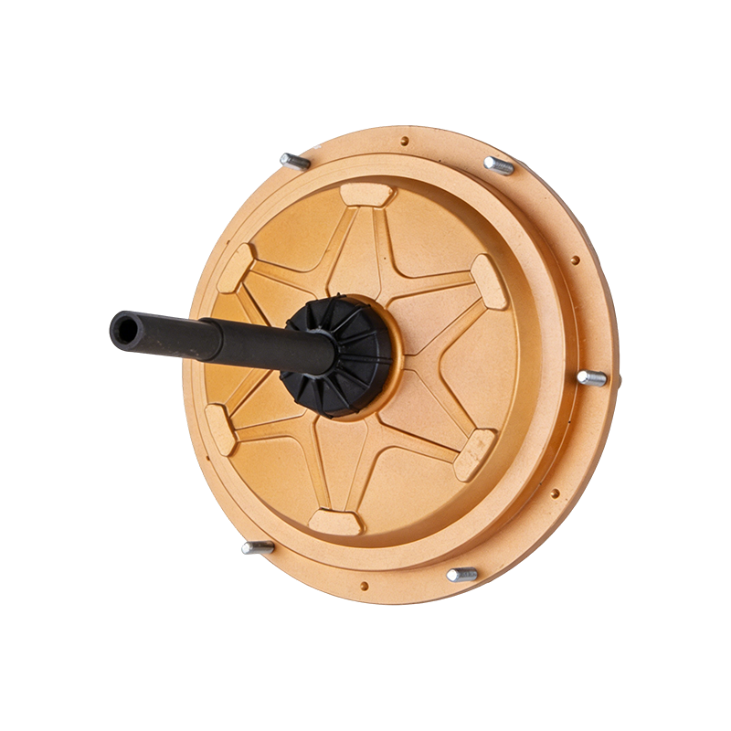 220V 600W External Rotor BLDC Air Cooler MotorThis 600W brushless motor is built for steady fan duty in evaporative coolers. Its direct 220V drive simplifies the electrical setup, but proper controller current limiting and mindful cable routing are essential in an industrial enclosure.View Product →
Installation, Shielding, and Thermal Management
The way you install the controller and route the cables is just as important as the electrical connection. A poorly mounted controller may overheat, and a long unshielded phase cable can cause EMI that corrupts the Hall signal. In an industrial enclosure, there is usually more than one motor drive, so plan the layout to keep sensitive signal wires away from high-current conductors.
Mount the Controller on a Heat Sink
The controller's MOSFETs and driving stage produce heat that must be transferred to the mounting surface. The metal plate of the controller will often be the heat sink itself. Use a silicone thermal pad or thermal grease between the controller and the mounting plate, and secure it with proper screws. Do not mount the controller inside a sealed plastic box without ventilation, because the heat will build up and cause thermal derating or shutdown.
Shielding and Cable Routing
In a typical industrial environment, the motor phase wires carry high-frequency PWM currents. The fast switching edges generate common-mode noise. If the long phase wires run parallel to the Hall sensor wires, the noise can couple into the sensor lines and cause false commutation signals. The simplest solution is to route the phase wires in a separate conduit or use a braided shield for the phase cable. You can also add a ferrite core on the Hall cable to suppress high-frequency noise. Keep the hall cable as short as practicable, ideally under 1 meter, to avoid voltage drop and interference.
Grounding and Current Return
Connect the controller ground and the motor ground to a common ground point. Avoid creating a ground loop where the signal ground and power ground are connected at multiple points. If the controller is supplied from a rectified AC source, the negative bus must be common to the DC link. Loose ground connections can trigger overvoltage spikes and destroy the Hall sensors or the control board.
Thermal Consideration for the Motor
What works for one power level may not work for another. A 850W external BLDC air cooler motor demands a bulkier heatsink and a more robust controller than a 600W unit. The controller's MOSFETs need to handle larger switching losses, and the motor's frame will run hotter at that power level. Always check the total system power budget and the ambient temperature of the application. An evaporative air cooler mounted in a hot warehouse may need an enclosure that keeps the controller below 50°C.
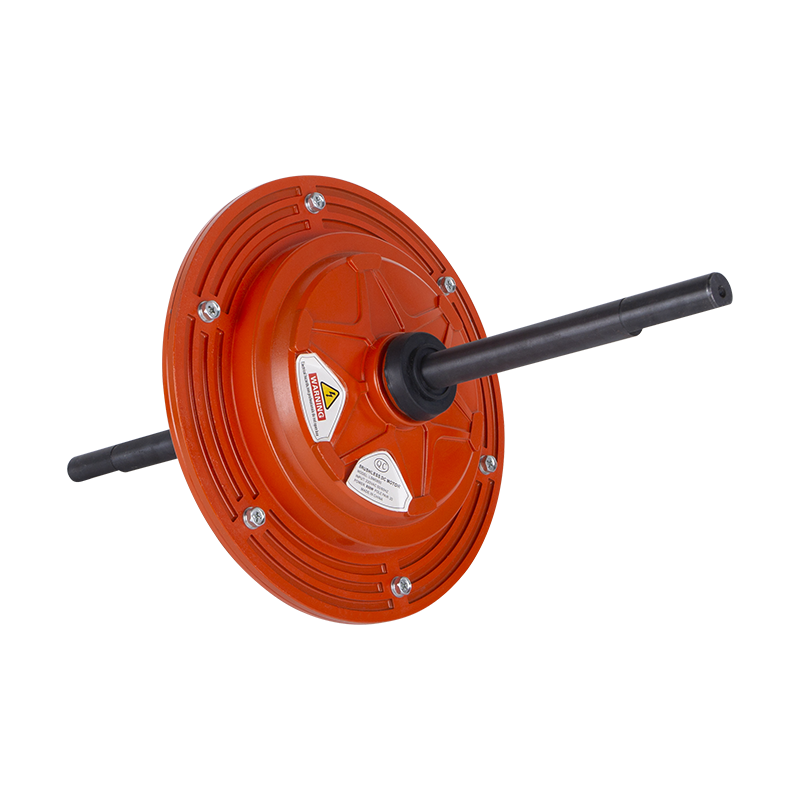
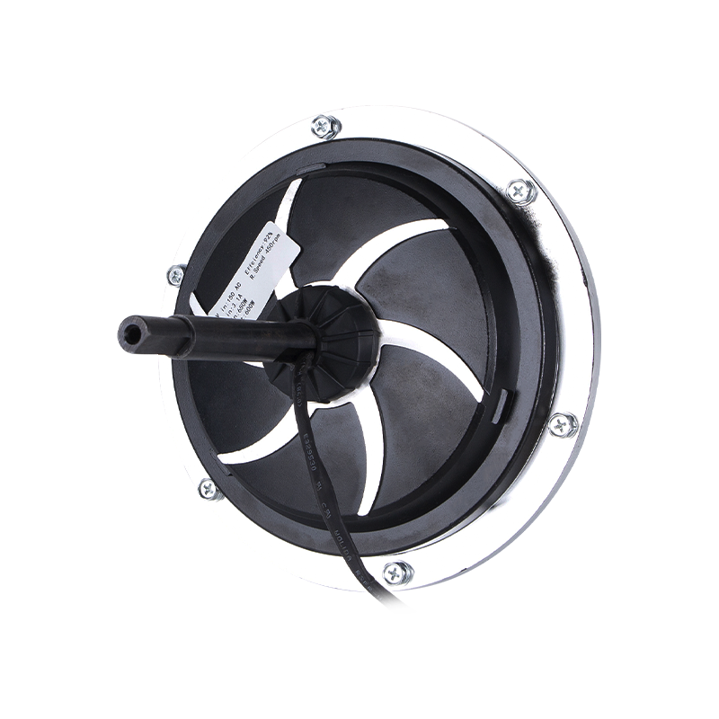 220V 850W BLDC Motor for High-Power Air Cooler ApplicationsWith an 850W rating, this external-rotor motor demands a robust controller and adequate heat dissipation. When testing, use current-limited supplies and observe phases carefully to avoid sudden jerks or wiring mistakes.View Product →
Safe Testing and Troubleshooting
After you have made all connections, the test phase is where you find any wiring mistakes. Use a current-limited power supply when possible, and observe the motor's behavior through a tachometer or current meter. Never test a BLDC motor by holding it with your fingers while the controller sequences the phases incorrectly. The motor can jerk violently, and the rotating parts may catch a loose sleeve or cable.
First Power-On Steps
Set the speed command to its lowest value, or disconnect the throttle and use an external 1V reference. Apply power at a slowly increasing DC bus voltage, or use a variac on the AC side if the controller has an integrated rectifier. Watch for excessive current on the ammeter. The no-load current of a BLDC motor should be a small fraction of its rated current. If you see the current climbing without any rotation, turn off the power immediately. This usually means a shorted phase wire or a Hall phasing error.
Measuring Back EMF
With the motor disconnected from the controller, you can measure the back EMF waveform on each phase by spinning the shaft with a drill. The three phases should produce a symmetrical sinusoidal waveform, with 120 degrees of phase shift between each phase. If the waveform is missing on one phase, there is an open winding or a disconnected wire. This back EMF test is useful before you ever apply controller power, and it does not require a controller at all.
Common Troubleshooting Table
| Symptom | Likely Cause | Corrective Action |
|---|---|---|
| No motion, high current draw | Hall signal wires swapped | Swap two Hall wires or re-order the sensor connection |
| Motor runs but vibrates at low speed | Hall supply voltage out of range | Check and correct the sensor supply voltage |
| Motor runs in the wrong direction | Phase order reversed or direction pin set incorrectly | Swap any two phase wires and swap any two Hall wires |
| Motor starts with a loud squeal and then calms | Phase sequence not matched to controller commutation table | Validate the phase order against the motor datasheet |
| Motor overheats under no load | Holding current due to wrong commutation or too low bus voltage | Correct the bus voltage and confirm commutation sequence |
| Intermittent stall when loaded | Current limiting set too low | Increase the controller current limit or use a higher-current controller |
Connecting BLDC Motors in Industrial Air Cooler Applications
The connection principles you have followed so far apply to almost every BLDC motor, but the practical details change when the motor sits inside an evaporative air cooler or a large industrial fan. These motors are often external rotor BLDC machines, meaning the rotor is the outer shell and the fan blades are mounted directly to that shell. This design makes the motor compact and well-suited to air-moving applications, where the impeller has a high moment of inertia and needs smooth, controlled acceleration.
When connecting an external BLDC air cooler motor, you also need to confirm that the motor's electrical and mechanical interface matches the controller. For example, a 220V external BLDC air cooler motor rated at 1500W is typically used in large industrial ventilation units. The bus voltage must be stable, the Hall connector must be rated for the motor's operating temperature, and the controller must be able to commute at the high-frequency PWM necessary for quiet fan operation.
In an industrial air-conditioning application, the motor may run for hours at a constant speed, and the airflow path can change with filters, louvers, and ambient conditions. The controller's current limit therefore has to be set to allow the motor to deliver torque when the fan blades are loaded, without creating a condition that overheats the winding. You can read more about the working principles of these motors in our guide to external BLDC air cooler motors.
For the large end of such fan systems, a 1500W motor is often paired with a 220V controller that can deliver at least 8A continuously. This combination is common in evaporative coolers for factories and warehouses, where the cooling load is high. The mounting plate and cable glands should be chosen carefully because the motor's mechanical vibration will be transferred to the controller if the controller is mounted directly on the motor shell. Use a damped mount or a separate enclosure.
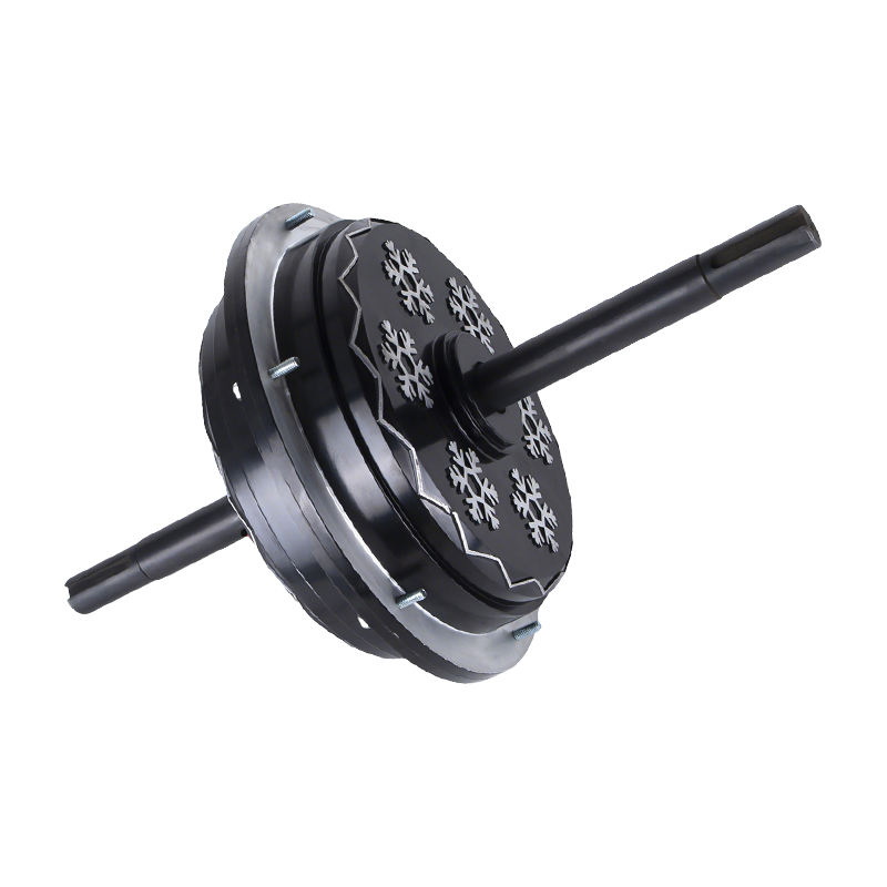
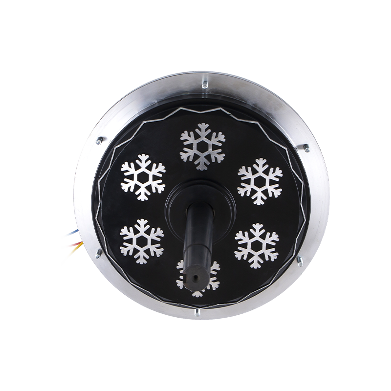 220V 1500W External Rotor BLDC Motor for Heavy-Duty CoolingThis 1500W motor is designed for large industrial evaporative coolers, typically paired with a controller providing at least 8A. To prevent vibration issues, mount it on a damped base or in a separate enclosure.View Product →
If you are designing a cooling equipment package, you can also review the industrial air conditioning application information to see how this product line fits into a complete system. The key takeaway is that the electrical connection is only half of the installation; the mechanical and thermal packaging must be matched to the application.
Common Mistakes to Avoid
Even experienced technicians can make simple mistakes when connecting a BLDC motor and controller. The following list covers the most frequent errors that lead to controller failures, motor damage, or unsafe operation.
- Applying voltage before checking the phase wire connection. If the phase wires are loose, the controller will see an open phase and may immediately current-limit or blow the fuse. Always check mechanical tightness first.
- Assuming Hall sensors are all the same. Some controllers provide 5V, others 12V. Overvoltage on a 5V Hall sensor causes permanent damage. Check the sensor specification.
- Ignoring the controller current limit. A busy workshop may have a controller that is rated for a different motor. Without setting the current limit correctly, the motor can run at an overload current and overheat the windings.
- Connecting the phase and Hall order without testing at reduced voltage. The very first test should be at a low bus voltage or a low PWM duty cycle. This catches mistakes before the controller delivers full power.
- Using insufficient wire gauge for the phase leads. A 1500W motor at 220V draws over 6A, so the phase conductors must be at least 18 AWG, and the DC input leads should be even larger. Thin wires cause voltage drop and generate heat at the terminals.
- Leaving unused Hall wires floating. If a controller has an unused Hall channel, it can pick up noise and cause random faults. Terminate unused Hall inputs with a resistor that matches the sensor output.
- Forgetting to set the direction pin. Many controllers have a low-speed input that determines the default direction. If you have physically wired the motor for clockwise rotation, setting a direction pin to counterclockwise will merely cut the phase, not reverse it. Plan the wire order and the software direction together.
- Testing without strain relief. Vibration eventually breaks crimped connections. Use strain relief on the motor cable and the controller connector to avoid intermittent failures later in service.
The connection of a BLDC motor to a controller is a systematic process that requires attention to phase order, Hall signals, voltage rating, current protection, and safe testing. Start with correct wire identification, verify the electrical ratings, connect the phase and Hall wires in the proper sequence, and then run a controlled first test. If anything sounds unusual or draws excessive current, stop immediately and revisit the phase and Hall wiring. With the correct setup, an industrial BLDC motor such as an external rotor air cooler motor will provide many years of quiet, efficient service. The same process you used for a small 600W fan also applies to a 1500W system, and the troubleshooting table will help you resolve the most common issues.
 Ready To Customise
 Your Motor Products?

We are professional motor manufacturers, delivering powerful, stable, and efficient power cores for all industries through precision craftsmanship and innovation.
Contact Us
-
 Mobile:+86 13575536911
-
 Tel:+86 18357538240
-
 Whatsapp:+8618357538240
-
 Email:betty@dbjxmotor.com
-
 Company Address
Copyright © by Shengzhou Jiangxin Motor Technology Co., Ltd. All Rights Reserved.
Wholesale Industrial Fan Motors Manufacturers
