

 English
 русский
 Español
 عربى
عربى

No. 8, Duxiu San Road, Ganlin Town, Shengzhou City, Shaoxing City, Zhejiang Province, China

News Category
Product Category
How Does a BLDC Motor Controller Work? PWM, Commutation, and Selection Tips
Content
When a 220V DC-powered external rotor BLDC air cooler motor spins up, you won't hear a commutator snap or see brush dust. The rotor turns smoothly, and its speed is regulated by a compact electronic circuit that sits somewhere inside the equipment. That circuit is the BLDC motor controller. Its job sounds simple: turn DC power into sequentially switched three-phase currents and know exactly when to switch them. The result is a self-synchronous motor that follows the stator field without mechanical contacts. The quality of that controller determines whether the motor runs quietly, efficiently, and for years without overheating.
What a BLDC Motor Controller Actually Does
A BLDC motor controller performs three main functions: start the motor, adjust speed, and control torque. It accepts a user command, such as a target speed or torque, detects the rotor position, and energizes the correct winding sequence at the right moment. Because the direction and magnitude of the currents in the three stator windings determine how the permanent-magnet rotor moves, the controller must know which winding to power and when to change it.
For a three-phase BLDC motor, the stator has three phase windings spaced 120 degrees apart. The rotor carries permanent magnets. The controller creates a rotating magnetic field that chases the rotor poles. As the rotor moves, the controller advances the commutation sequence so the field keeps pulling the rotor forward. In a brushed DC motor, the mechanical commutator and brushes perform this switching. In a BLDC motor, the controller does it electronically, which is why it is often called electronic commutation.
Core Components of a BLDC Motor Controller
Every BLDC controller, from a simple fan driver to a servo amplifier, consists of a few essential blocks. Each block must work together within microseconds:
- Microcontroller or DSP: executes the commutation algorithm, computes PWM duty cycles, and manages fault conditions.
- Gate driver: converts the low-voltage logic signals from the microcontroller into high-voltage gate voltages that turn power switches on and off.
- Power stage (MOSFETs or IGBTs): forms the three-phase inverter bridge that switches the main motor current.
- Position sensor: Hall effect sensors, an encoder, or a BEMF detection circuit that tells the controller where the rotor is.
- Current sensors: measure phase current for torque control and overcurrent protection.
- Power supply: supplies clean DC voltage to the control circuitry and sensors.
This whole assembly forms a real-time closed loop. The microcontroller reads rotor position and current feedback many times per second and updates the next switching state. Without position or current feedback, a controller can only run in open-loop mode, which leads to poor efficiency, missed commutation, and possible damage.
How Rotor Position Is Detected
Rotor position detection is the foundation of BLDC control. The controller must know where the magnet rotor is before it can switch the next phase. There are two mainstream methods.
The first uses Hall effect sensors. Three Hall sensors are placed 120 electrical degrees apart on the stator. As the rotor poles sweep past them, the sensors produce digital high/low patterns that tell the microcontroller which of six sectors the rotor is currently in. This method is simple, robust, and widely used in low-cost industrial equipment. The downside is the extra sensor wiring and the sensitivity to temperature and magnetic interference.
The second method is sensorless control. It detects the zero crossings of the back electromotive force (BEMF) in the unenergized phase winding. As the rotor spins, each winding generates an induced EMF. The point where this EMF changes polarity indicates a known rotor alignment. By sensing those zero crossings, the controller can calculate the next commutation point. Sensorless control saves wiring and component cost, but at very low speeds the BEMF is too weak to measure, so the motor needs a startup routine to spin it up before switching to closed-loop operation.
For fan and cooling equipment, including external rotor BLDC air cooler motors, the operating speed is usually high enough for sensorless control. However, applications requiring precise low-speed positioning prefer Hall sensors.
Commutation: Six-Step and FOC
Once the rotor position is known, the controller decides which switching pattern to apply. The most basic method is six-step commutation, also called trapezoidal or block commutation. It divides each electrical cycle into six sectors. In each sector, two windings are energized while the third is left floating. Current flows through one winding into the center and out the other, creating a magnetic vector that advances in steps. This approach is easy to implement in a microcontroller and uses simple Hall sensor logic.
The limitation is that the current waveform is rectangular, which produces torque ripple. At lower speeds, the ripple can translate into audible noise and mechanical vibration.
Field-oriented control, or FOC, is more advanced. It transforms the three-phase currents into a rotating d-q coordinate system, where the d-axis aligns with the rotor magnet flux and the q-axis controls torque. By regulating the current in this reference frame, the motor behaves like a separately excited DC machine. FOC produces nearly sinusoidal phase currents, which yields smooth torque across the entire speed range. The cost is higher computational effort, a fast microcontroller, and more complex current sensing.
| Characteristic | Six-Step | FOC |
|---|---|---|
| Current shape | Rectangular | Sinusoidal |
| Torque ripple | Present | Low |
| Low-speed performance | Moderate | Excellent |
| Computational load | Low | High |
| Implementation cost | Lower | Higher |
| Typical use | Fans, pumps, and blowers | Servo drives, robots, precision tools |
For large external rotor BLDC air cooler motors, six-step is often sufficient. But when the design target is low noise and a wide speed range, a FOC controller becomes the better choice, especially at higher power levels.
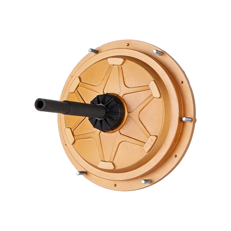
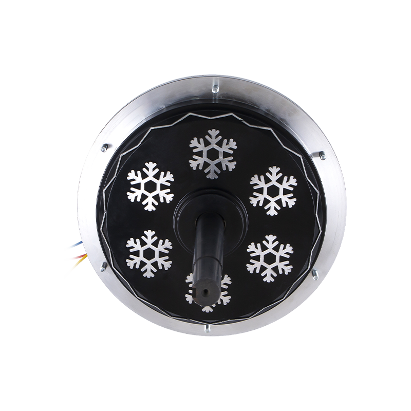 DC198 220V 1500W External Rotor BLDC Motor for Air CoolersThis high-power brushless motor is built for heavy-duty evaporative coolers, featuring pure copper windings, IP54 protection, and F-class insulation for reliable operation in harsh industrial environments.View Product →
PWM Current Control and Torque
After the commutation sequence is chosen, the controller must regulate voltage and current. Most controllers use pulse-width modulation (PWM). In PWM, the power switches are turned on and off at a fixed frequency, often between 10 kHz and 30 kHz. By changing the on-time ratio, or duty cycle, the controller sets the average voltage applied to the windings. A 50% duty cycle means the switch is on half the time in each PWM period, yielding approximately half the bus voltage.
For torque control, current is the more important variable. In a BLDC motor, the developed torque is proportional to the phase current, at least below magnetic saturation. The controller measures current using a shunt resistor or current transformer, compares it to a reference value, and adjusts the PWM duty cycle to force the actual current to follow the reference. This is a current feedback loop, and it is what gives the motor its stiffness and responsiveness.
Robust protection features should be part of any serious controller. Overcurrent protection, over-temperature shutdown, undervoltage lockout, and stall detection all prevent early failure. For buyers comparing controllers, the presence of these protections matters as much as the rated power.
Matching a Controller to a BLDC Fan Motor
Matching a controller to a motor is not just a matter of voltage class. The bus voltage, peak phase current, back EMF constant, Hall sensor phasing, speed range, and load torque profile all have to be compatible.
Consider one of our external rotor BLDC air cooler motors: the DC149 series runs on 220V DC input and covers power levels from 600W to 850W. This type of motor is typically mounted in evaporative cooling equipment. The load is a fan, which follows a square torque curve. Start-up current can be two to three times the rated current, so the controller must be able to deliver a short-term overload without tripping. At the same time, flickering input voltage from the grid can affect the DC bus, so a robust controller needs a wide input voltage tolerance and good regulation.
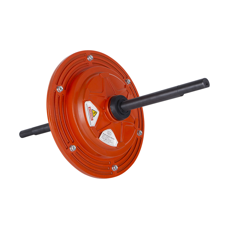
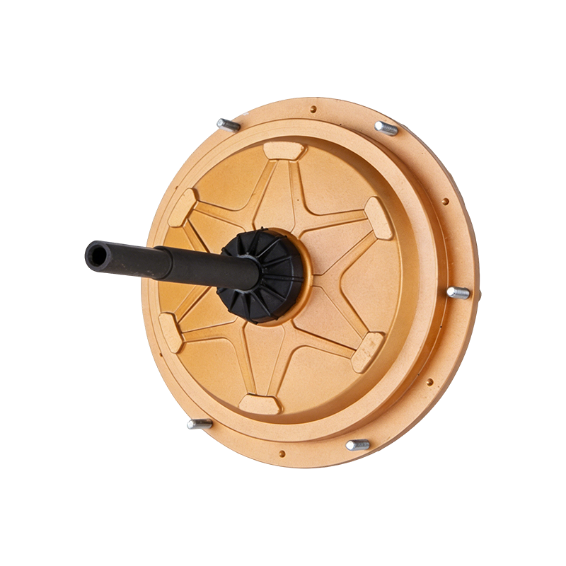 DC149 220V 600W External Rotor BLDC Motor for Air CoolersThis 600W brushless motor offers direct 220V drive, high torque, and a long maintenance-free lifespan, making it suitable for continuous heavy-duty cooling applications in workshops and warehouses.View Product →
Another practical point is thermal design. A controller that runs in a hot enclosure will derate its output. If the air cooler motor is installed in a tight, dust-filled environment, the controller’s board must be conformal-coated and its power stage must have enough copper area or forced airflow. These choices impact the total system cost and reliability. For manufacturers of air handling equipment, comparing controller protection and derating curves is an essential part of supplier evaluation. We have more detail on industrial fan applications that can help you frame those requirements.
Practical Considerations in Fan and Cooling Equipment
Fan and cooling equipment impose special demands on BLDC motor control. Unlike a constant-torque load, a fan is a quadratic torque load: torque rises with the square of speed, and power rises with the cube. This means the controller must manage a very light load at low speed and a steeply increasing load at high speed. A controller that is tuned for a servo motor may not handle this characteristic well.
Moreover, many fans use external rotor motors, where the rotor is the outer shell and the stator is inside. The motor is often built directly into the fan impeller, leaving limited space for the controller. In some products, the controller is integrated into the motor terminal box or even mounted on a separate PCB inside the fan housing. This integration affects how heat is dissipated and how the controller is protected from humidity and dust.
For EC fans, the controller is an integral part of the motor assembly. The fan takes in AC line voltage, rectifies it to DC, and then uses the BLDC controller to drive the motor. Users simply connect the fan to AC power and get the energy savings of a DC drive without needing an external VFD. Our ECF35010 series is a good example of this compact EC design, using 220V input and 350W output.
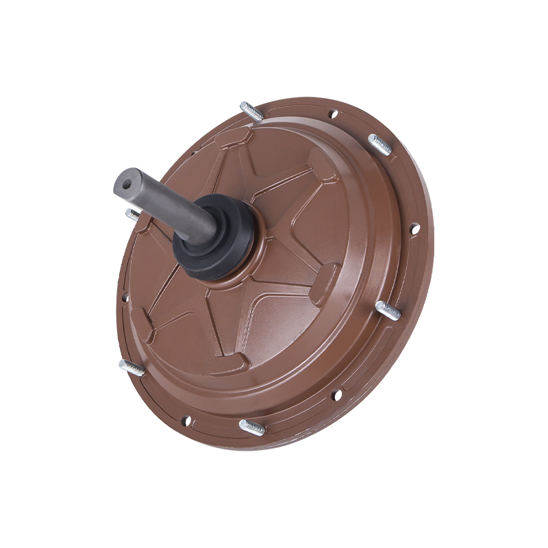
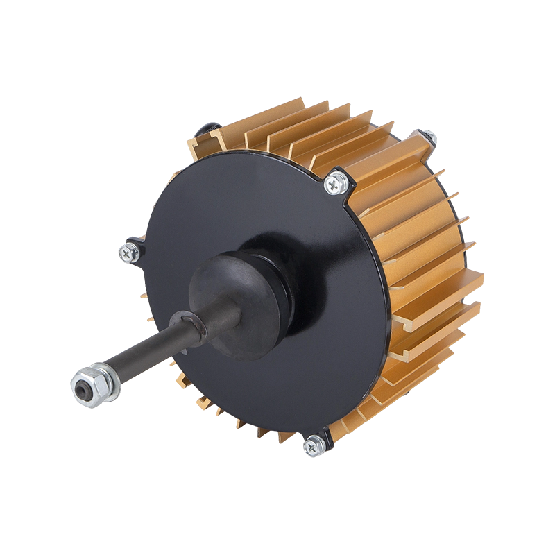 ECF-350-10 220V 350W Electronically Commutated Fan MotorThis EC fan motor integrates a BLDC controller and rectifier, achieving up to 95% efficiency and low noise, ideal for evaporative air coolers where energy savings and quiet operation are priorities.View Product →
When selecting an external rotor BLDC motor for air cooler applications, the controller’s current rating and the motor’s resistance and inductance must be matched. A controller that is undersized will overheat; one that is oversized can result in unnecessary cost and wasted space. A useful reference is our article on external BLDC air cooler motor design considerations.
Conclusion
BLDC motor controllers are the intelligence behind every brushless motor. They use position feedback, commutation logic, and PWM to turn DC electricity into continuously rotating torque. The choice between six-step and FOC affects smoothness, cost, and complexity, while the matching of voltage and current ratings determines whether a motor runs safely at full load. For engineers and buyers working with air coolers, EC fans, and other industrial blowers, understanding how a BLDC controller works is the first step toward selecting a reliable motor and controller combination.
 Ready To Customise
 Your Motor Products?

We are professional motor manufacturers, delivering powerful, stable, and efficient power cores for all industries through precision craftsmanship and innovation.
Contact Us
-
 Mobile:+86 13575536911
-
 Tel:+86 18357538240
-
 Whatsapp:+8618357538240
-
 Email:betty@dbjxmotor.com
-
 Company Address
Copyright © by Shengzhou Jiangxin Motor Technology Co., Ltd. All Rights Reserved.
Wholesale Industrial Fan Motors Manufacturers
