

 English
 русский
 Español
 عربى

No. 8, Duxiu San Road, Ganlin Town, Shengzhou City, Shaoxing City, Zhejiang Province, China

News Category
Product Category
How to Calculate PWM Frequency for a BLDC Motor: Four Practical Checks
Content
- 1 Four Different Frequencies Get Called "the PWM Frequency"
- 2 Step One: Collect Winding Data You Can Actually Defend
- 3 Step Two: The RL Cutoff Gives You the Lower Bound
- 4 Step Three: Current Ripple Sets the Real Floor
- 5 Step Four: Keep Enough Switching Cycles per Commutation Step
- 6 Step Five: Test the Candidate Against the Ceiling
- 7 A Worked Comparison Across Two Motor Classes
- 8 What Integrated Drives Mean for Your Calculation
- 9 Validation on the Bench: Four Measurements That Settle the Argument
- 10 Mistakes That Recur in Real Projects
- 11 Where the Calculation Lands in Practice
A 600 W external-rotor BLDC air cooler motor leaves the assembly line running at an 8 kHz carrier. On the test bench the blades emit a hard whine, the winding surface climbs 22 degrees C above the draw-off temperature, and the phase current trace shows a ripple band nearly half as wide as the fundamental. Nothing is defective. The drive simply was never matched to the winding.
The short answer to how to calculate PWM frequency for a BLDC motor is that you are not picking one number, you are solving for the largest of three floors and then checking a ceiling. The floors come from the winding's electrical time constant, the allowed peak-to-peak current ripple, and the motor's electrical (commutation) frequency at top speed. The ceiling comes from switching loss, dead time, gate-drive budget and the counter resolution of the microcontroller. For a 220 V external-rotor fan motor in the 350 W to 1500 W class with 8 to 12 mH of phase inductance, the three floors usually converge somewhere between 12 kHz and 20 kHz. For a low-inductance high-speed motor with 100 to 200 microhenry of phase inductance, the same arithmetic pushes you to 40 kHz or beyond, and the ceiling check starts to bite hard.
What follows is the calculation sequence in the order that keeps you out of trouble: gather defensible winding data, compute the RL cutoff, compute the ripple floor, compute the commutation floor, then test the chosen value against the loss and timing ceiling before you write it into the firmware.
Four Different Frequencies Get Called "the PWM Frequency"
Most of the confusion in this topic comes from mixing up four separate frequencies that all appear in a BLDC drive. Only one of them is loaded into the timer register.
| Quantity | Definition | Reference value | Where it is set |
|---|---|---|---|
| Mechanical speed | Shaft revolutions per minute | 1300 rpm | Application requirement |
| Electrical frequency | rpm x pole pairs / 60 | 86.7 Hz (4 pole pairs) | Result of speed and magnet count |
| Commutation step rate | Six-step: 6 x electrical frequency; field-oriented control: one sector update per electrical cycle | 520 Hz for six-step | Control algorithm |
| Carrier frequency | Power-stage switching frequency | 12 to 20 kHz | This is the number we are calculating |
| Command PWM | Speed or torque setpoint signal fed into the drive, separate from the power stage | 100 Hz to 2 kHz | Host controller or PLC |
The last row deserves a warning. Plenty of field failures blamed on "wrong PWM frequency" turn out to be a command signal problem. A drive that expects a 1 kHz, 10 to 90 percent duty command and receives a 20 kHz signal will either ignore it or read a stuck duty cycle, because the input filter and the capture routine were designed around a much slower waveform. Check the interface specification before you touch the carrier.
Step One: Collect Winding Data You Can Actually Defend
The calculation is only as good as the inductance and resistance values behind it, and datasheets are frequently careless with both. Three habits pay off.
Measure per phase, not line to line
An LCR meter placed across two terminals reads the series combination of two phases. For a balanced wye winding the per-phase value is half of that reading, but only if the rotor is stationary and the third terminal is floating. Record which convention you used, because a factor-of-two error here shifts the ripple floor by a factor of two.
Measure at a frequency near your intended carrier
Laminations, eddy currents and skin effect make inductance frequency dependent. A winding that reads 10 mH at 100 Hz may read 8 mH at 10 kHz and 7 mH at 20 kHz. Since ripple is what you are sizing against, use the value at the frequency band you plan to run, and note the meter's test frequency on the test sheet.
Use the hot, saturated worst case
Copper resistance rises about 0.393 percent per degree C. A phase resistance of 1.10 ohm at 25 degrees C becomes roughly 1.42 ohm at a 100 degree C winding, which lifts the RL cutoff by nearly 30 percent. Inductance moves the other way under load: at twice rated current, a fan winding can lose 30 to 50 percent of its small-signal inductance as the magnetic circuit approaches saturation, and the ripple floor rises proportionally. Audit both excursions.
Write down five numbers before calculating anything: per-phase resistance at 25 degrees C, per-phase inductance at the intended carrier frequency, magnet count (pole pairs = magnets / 2), rated phase current, and the DC bus voltage including the highest realistic case. A 220 V motor fed from an active power-factor-correction stage sees 380 to 400 V DC rather than 310 V, which is a 25 percent ripple penalty that many first prototypes miss.
Step Two: The RL Cutoff Gives You the Lower Bound
Each phase is a series resistor and inductor, and that pair forms a first-order low-pass filter. Its cutoff frequency is:
f_c = R / (2 x pi x L)
Below this frequency the current can follow the commanded average within a switching cycle. Above it, the winding starts to average the applied voltage for you. The widely quoted rule of thumb is to run the carrier at ten times the cutoff or more, which gives the current loop enough bandwidth to hold the commanded value and keeps the current waveform from lagging the voltage command by a large phase angle.
Note what the cutoff itself is not. The formula f = R / (2 x pi x L) that circulates on forums is the cutoff, not a recommended carrier. Running a BLDC motor at its own RL cutoff frequency produces heavy torque ripple and audible noise, because the winding cannot smooth anything at that rate.
Using the reference motor: R = 1.10 ohm at 25 degrees C, L = 8 mH measured at 10 kHz. The time constant is 8 mH / 1.10 ohm = 7.3 ms, and f_c = 1 / (2 x pi x 7.3 ms) = 21.9 Hz. Ten times that is 219 Hz. Corrected to a hot winding of 1.42 ohm, the cutoff is 28.3 Hz and the ten-times floor is 283 Hz.
For a medium-inductance fan motor the RL floor is therefore trivial. It only becomes binding on very low-inductance machines, and on motors where a designer has deliberately added series inductance. Treat it as a sanity floor, not the answer.
Step Three: Current Ripple Sets the Real Floor
This is the calculation that actually decides the number for most drives. During one switching period the applied voltage charges the winding inductance, and the peak-to-peak ripple current is:
delta_I = V_bus x D x (1 - D) / (L x f_pwm)
where D is the instantaneous duty of that leg. The expression peaks at D = 0.5, which simplifies the worst case to V_bus / (4 x L x f_pwm). Rearranged for the frequency you need:
f_pwm is greater than or equal to V_bus / (4 x L x delta_I_allow)
Choose delta_I_allow as a fraction of rated phase current. Ten to twenty percent keeps iron and copper losses modest and gives the current loop an easy target; above thirty percent you start to see extra heating, audible noise and, in sensorless drives, a noisier back-EMF observation.
Reference motor again: V_bus 310 V DC, L 8 mH, rated phase current 2.5 A, allowed ripple 20 percent, so delta_I_allow = 0.5 A peak to peak.
f_pwm is greater than or equal to 310 / (4 x 0.008 x 0.5) = 310 / 0.016 = 19,375 Hz
That rounds to 20 kHz. At 12 kHz the same motor carries 0.81 A of ripple, roughly 32 percent of rated, and at 8 kHz it carries 0.97 A, close to 39 percent. That is exactly the ripple band visible on the failing drive from the opening paragraph, and it explains both the whine and the extra 22 degrees C.
Three corrections improve the estimate. Space-vector modulation with third-harmonic injection produces roughly 15 percent less worst-case ripple than the sinusoidal expression above, so a 20 kHz estimate often behaves like 18 kHz. If the motor runs at low modulation index for most of its duty, the worst case at D = 0.5 may never occur at the operating point, and you can trade some ripple margin for lower switching loss. Conversely, if the motor must survive a locked rotor or a deep voltage sag, the duty will sweep through 0.5 and the worst case becomes real.
Step Four: Keep Enough Switching Cycles per Commutation Step
The carrier also has to be fast relative to the motor's electrical frequency, otherwise the drive has too few opportunities per sector to regulate current. Compute the electrical frequency first:
f_elec = rpm x pole pairs / 60
For the reference motor at 1300 rpm with four pole pairs, f_elec = 86.7 Hz. In six-step commutation each electrical cycle contains six steps, so the step rate is 520 Hz. A common guideline is at least ten, preferably twenty, PWM periods per commutation step, which puts the floor at 5.2 to 10.4 kHz. Notice that this now exceeds the RL floor and is approaching the ripple floor, which is why fan drives in this class cluster around 12 to 16 kHz.
Field-oriented control has a slightly different constraint. The current loop typically updates once per carrier period, so the carrier must be at least ten times the electrical frequency to keep the loop stable at top speed, and much more if you want low torque ripple at low speed. Single-shunt current sensing adds a harder limit: the shunt is only readable during defined windows of the switching period, so at very high duty the measurement windows shrink and the drive either skips measurements or lowers the carrier.
High-speed motors break the guideline entirely. A 20,000 rpm motor with four pole pairs has f_elec = 1333 Hz and a six-step rate of 8 kHz. Demanding twenty PWM periods per step would require 160 kHz, which is impractical for an insulated-gate bipolar transistor bridge and expensive even with silicon carbide. Real drives in that regime switch to one effective pulse per commutation step, synchronising the PWM to the commutation event instead of running free. The wider point stands: if your electrical frequency approaches a few kilohertz, the carrier calculation must be done together with the modulation scheme, not separately.
If you want the switching sequence and sector timing in more depth, this explanation of how a BLDC controller turns PWM into commutation walks through the gate pattern step by step.
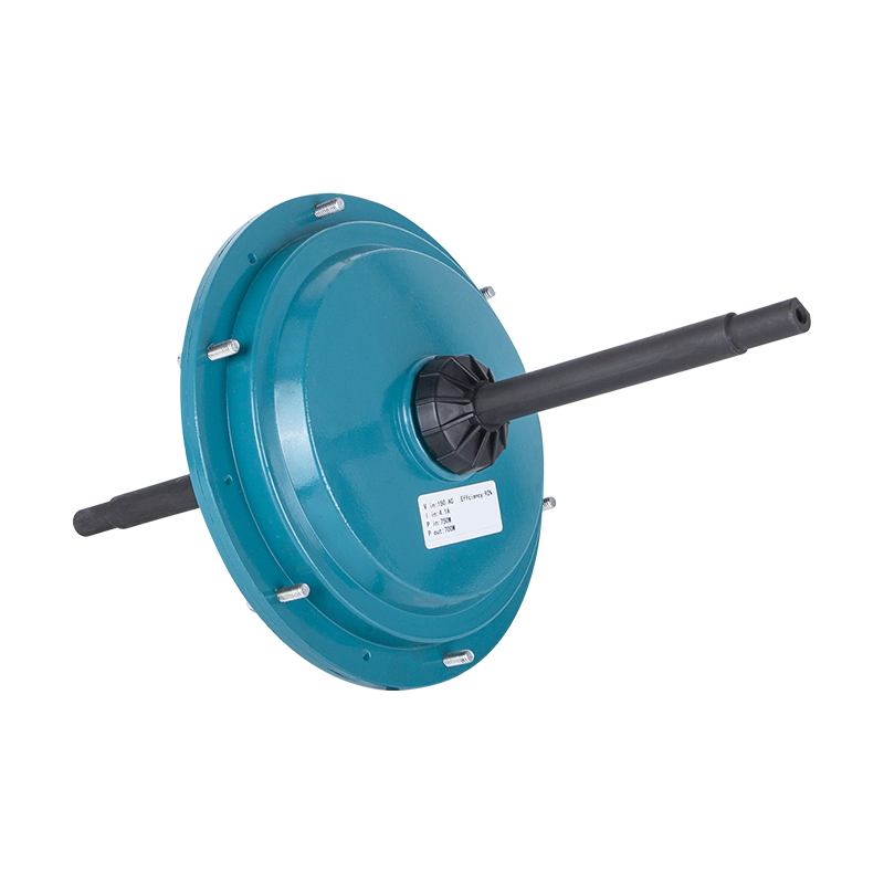
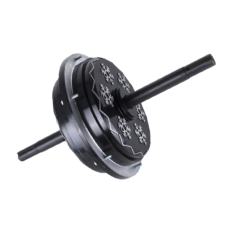
Taking the reference fan motor as a case, the 220 V 600 W external-rotor design in the DC149 series is a realistic match for these numbers, and its published winding data is a useful cross-check against your own bench measurements.
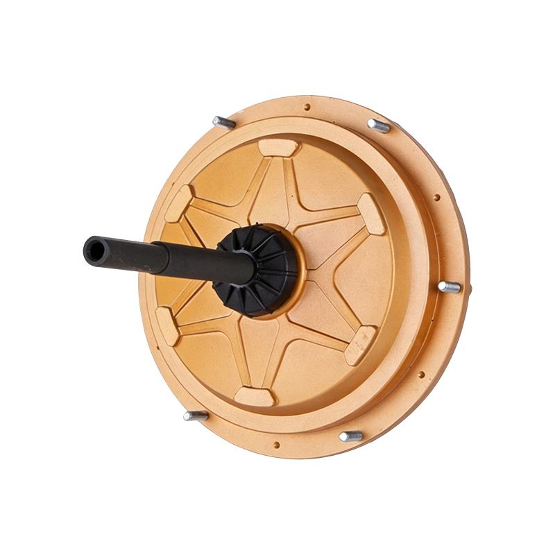 DC149 220 V 600 W External-Rotor BLDC Air Cooler Motor220 V 600 W external-rotor BLDC motor for air coolers, with published winding data that can be cross-checked against bench measurements.View Product →
Step Five: Test the Candidate Against the Ceiling
Once the floors are known, the upper limit decides how much margin you can afford. Four constraints matter, and the first two usually bind first.
Switching loss
A rough per-device estimate is P_sw = 0.5 x V_bus x I_phase x (t_on + t_off) x f_pwm. With a 310 V bus, 3.5 A peak phase current, 100 ns of combined transition time and a 16 kHz carrier, each device dissipates about 0.87 W from switching alone. At 20 kHz that becomes 1.08 W, and at 8 kHz it falls to 0.43 W. Multiply by the number of devices active in your modulation scheme, add conduction loss, and check against the thermal resistance of the package and heatsink. A 25 degree C junction margin at the worst ambient is a sensible design target, and it is the number that usually kills an ambitious 40 kHz plan on a naturally cooled board.
Dead time and minimum pulse width
Dead time is a fixed tax on duty cycle. At 16 kHz the period is 62.5 microseconds, so a 1 microsecond dead time costs 1.6 percent of the period; at 5 percent commanded duty that is a 32 percent error in the applied voltage, producing current distortion and low-speed torque ripple. Shorter dead times reduce the error but raise shoot-through risk as junction temperature rises and device delays drift. Many gate drivers also specify a minimum input pulse, typically 50 to 200 ns, which caps the usable duty range at high carrier frequencies.
Timer resolution
A 100 MHz timer in centre-aligned mode gives 6250 counts per period at 16 kHz, so the duty step is about 0.016 percent. At 80 kHz the same timer yields 1250 counts and 0.08 percent steps. Both are workable, but the coarse case limits fine current regulation at light load.
Acoustic noise and EMC
The 8 to 12 kHz band is the worst place to sit for human hearing, which is one reason 8 kHz drives sound so unpleasant. Moving to 16 kHz helps most adults but not everyone; 20 kHz and above is usually inaudible but pushes loss and radiated emissions up. Random or dithered carrier modulation spreads the spectrum and takes the pure tone out, at the cost of slightly higher current ripple and a more complex current-sampling scheme. On the EMC side, higher carrier frequencies make the input filter and the motor cable behave worse, so a design that passes at 12 kHz is not automatically compliant at 24 kHz.
A Worked Comparison Across Two Motor Classes
The same four checks produce very different answers depending on winding inductance. The table below runs a medium-inductance fan motor and a low-inductance high-speed motor through the identical arithmetic.
| Parameter | Air cooler fan motor | High-speed blower motor |
|---|---|---|
| DC bus | 310 V | 48 V |
| Phase resistance at 25 C | 1.10 ohm | 0.05 ohm |
| Phase inductance at carrier | 8 mH | 120 microhenry |
| Pole pairs | 4 | 4 |
| Maximum speed | 1300 rpm | 20,000 rpm |
| Rated phase current | 2.5 A | 20 A |
| RL cutoff | 21.9 Hz | 66 Hz |
| Ten-times RL floor | 219 Hz | 663 Hz |
| Allowed ripple (20 percent, 15 percent) | 0.5 A | 3 A |
| Ripple floor | 19.4 kHz | 33.3 kHz |
| Electrical frequency at top speed | 86.7 Hz | 1333 Hz |
| Commutation floor (20 periods per step) | 10.4 kHz | 160 kHz, not achievable |
| Selected carrier | 20 kHz | 40 kHz with PWM synchronised to commutation |
The high-speed column is the more instructive one. Its ripple floor of 33 kHz is already high for a 48 V bridge, and the commutation guideline is unreachable, so the design has to accept fewer PWM periods per step and compensate with tighter current-loop timing and better back-EMF filtering. That is a normal engineering compromise, not a mistake, but it has to be a conscious one. If you buy such a motor with an integrated controller, the compromise is already baked into the firmware and you cannot change it.
What Integrated Drives Mean for Your Calculation
Many fan and air cooler motors now ship with the inverter mounted on the end shield, and the carrier frequency is fixed at whatever the drive manufacturer chose, commonly 16 to 20 kHz. For the buyer, the arithmetic above becomes a verification exercise rather than a design exercise.
Ask for the switching frequency in writing, and ask whether it is fixed or configurable. Then ask the two questions that reveal whether the number was chosen deliberately: what is the measured peak-to-peak ripple at rated load, and what is the junction temperature margin at the maximum rated ambient. A supplier who can answer both has done the calculation. A supplier who quotes only a frequency has not.
Also confirm which PWM the datasheet is describing. Electronically commutated fan motors in the 350 W to 1500 W class typically accept a 0 to 10 V analogue or a low-frequency PWM command while running a fixed internal carrier, and confusing the two will produce a commissioning problem that looks like a firmware fault.
For a 380 V installation where the drive is already integrated and the carrier is fixed, the practical check is whether the winding inductance and the published ripple are consistent at that carrier, which is the question worth putting to the supplier of a 380 V 1500 W EC fan motor.
 ECF160 380 V 1500 W EC Fan Motor for Evaporative Coolers380 V 1500 W EC fan motor for evaporative coolers; its winding inductance and published ripple can be checked at a fixed carrier.View Product →
Validation on the Bench: Four Measurements That Settle the Argument
Calculations narrow the field; measurements pick the winner. Run these four tests at the candidate frequency and at one step either side of it, for example 12, 16 and 20 kHz.
- Current ripple. Capture phase current with a compensated shunt or a high-bandwidth probe, at 25 percent, 50 percent and 100 percent load. Compare the peak-to-peak band against your allowed value. Watch for ripple that grows faster than predicted with load, which signals inductance saturation.
- Winding and device temperature. Soak at rated load until temperatures stabilise, then compare the two or three candidates. A 2 to 4 degree C difference in winding rise between 16 and 20 kHz is typical and tells you what the extra switching loss is buying.
- Efficiency at the operating point. Measure input DC power and shaft or air power at the application's real duty cycle, not at a single nominal point. Fan loads follow a cube law, so most of the annual energy is spent well below full speed, where the carrier and the modulation scheme matter more than at rated load.
- Acoustic sweep. Run the motor from 10 to 100 percent speed at each candidate carrier and listen for tones. Pay attention to structural resonances in the fan housing, since a carrier that is silent at one speed can excite a bracket resonance at another.
Keep the measurement sheet with the design record. When a customer reports a noise complaint two years later, the difference between a deliberate 16 kHz choice and an accidental one becomes very visible.
Mistakes That Recur in Real Projects
- Using the datasheet inductance without a test frequency. A value taken at 100 Hz can overstate the ripple performance by 20 percent or more.
- Forgetting the power-factor-correction bus. Ripple scales with bus voltage, so a 220 V motor on a 390 V DC link carries 26 percent more ripple than the same motor on a 310 V link.
- Sizing at 25 degrees C only. Hot resistance raises the RL cutoff, and saturation lowers inductance; both push the ripple floor up.
- Assuming a higher carrier is always better. Above roughly 24 kHz on a naturally cooled board, switching loss and dead-time distortion often cost more than the ripple improvement buys.
- Confusing the command PWM with the carrier. They are different signals with different specifications, and a mismatch looks like a control fault.
- Changing the carrier without re-tuning the current loop. Loop gains that suit 8 kHz are usually too aggressive at 20 kHz, and the symptom is oscillation under load steps.
Where the Calculation Lands in Practice
For an evaporative air cooler or an industrial fan duty motor in the 350 W to 1500 W range with 6 to 12 mH of phase inductance, the arithmetic converges on 12 to 20 kHz, and 16 kHz is a reasonable default with 20 kHz as the upgrade path when ripple or noise demands it. Below 8 kHz, medium-inductance windings carry too much ripple to stay quiet and cool. Above 24 kHz, the switching and dead-time costs usually outweigh the benefit on a convection-cooled bridge. For high-speed, low-inductance motors the floor climbs to 30 to 40 kHz and the modulation scheme has to be reconsidered at the same time.
When the motor and the drive are specified together, the cleanest arrangement is to fix the carrier, publish the winding inductance and resistance at that carrier, and state the ripple at rated load. For a 220 V 1500 W external-rotor air cooler motor running a fixed internal carrier, that combination is what makes the noise and thermal behaviour predictable before the first prototype is built.
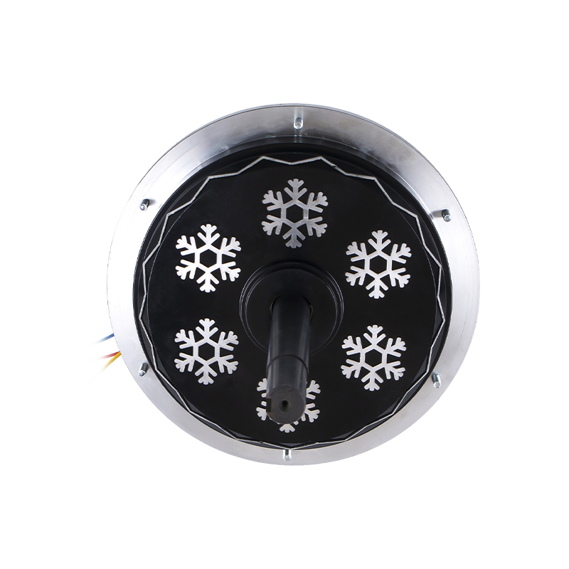 DC198 220 V 1500 W External-Rotor BLDC Air Cooler Motor220 V 1500 W external-rotor BLDC air cooler motor for fixed-carrier drive pairing, where winding inductance and rated-load ripple make noise and thermal behavior predictable.View Product →
The working checklist is short. Measure per-phase inductance at your carrier frequency and at the hot, saturated condition. Compute the RL cutoff and multiply by ten. Compute the ripple floor from V_bus / (4 x L x delta_I_allow) at D = 0.5. Compute the electrical frequency and confirm you still get ten or more switching periods per commutation step, or change the modulation scheme if you do not. Then check switching loss, dead time and timer resolution at the chosen value, and confirm with a bench sweep across three candidate frequencies. Do that once per motor-drive pairing and the question stops being a guess.
 Ready To Customise
Your Motor Products?

We are professional motor manufacturers, delivering powerful, stable, and efficient power cores for all industries through precision craftsmanship and innovation.
Contact Us
-
 Mobile:+86 13575536911
-
 Tel:+86 18357538240
-
 Whatsapp:+8618357538240
-
 Email:betty@dbjxmotor.com
-
 Company Address
Copyright © by Shengzhou Jiangxin Motor Technology Co., Ltd. All Rights Reserved.
Wholesale Industrial Fan Motors Manufacturers
