

 English
 русский
 Español
 عربى

No. 8, Duxiu San Road, Ganlin Town, Shengzhou City, Shaoxing City, Zhejiang Province, China

News Category
Product Category
Can a BLDC Motor Work as a Generator? A Practical Guide for Buyers and Builders
Content
- 1 The Short Answer: Yes, With Three Conditions
- 2 The Physics Is Symmetrical
- 3 What Actually Comes Out of the Three Leads
- 4 The Parameters That Decide Whether It Works
- 5 A Motor Is Not a Purpose-Built Generator
- 6 Where the Motor-as-Generator Approach Actually Works
- 7 Where It Falls Apart: Practical Failure Modes
- 8 A Worked Sizing Example
- 9 What to Put in an RFQ to a Motor Factory
Spin the shaft of a three-phase evaporative air cooler motor by hand and put a meter across two of its leads. You will read a few volts. Couple it to a drill and take it to 1,500 rpm and the reading climbs into the tens or hundreds of volts, with no rewinding, no modification and no controller attached. That single bench test answers the question that brings most buyers to this topic: a BLDC motor is a permanent-magnet synchronous machine, and a permanent-magnet synchronous machine does not know whether torque is going into the shaft or coming out of it. Yes, it works as a generator.
The more useful question is not whether it can generate, but whether it can generate something you can actually use. A bare BLDC motor will produce volts, but how many volts, at what speed, into what load, with what regulation and for how long before the winding gets hot, depends entirely on how the machine was wound and how it is being driven. Those are commercial decisions as much as technical ones, and they are the reason generator projects succeed or fail long before anyone opens a datasheet.
The Short Answer: Yes, With Three Conditions
A brushless DC motor generates whenever its rotor turns, because the magnets on the rotor sweep past the stator coils and induce a voltage in them. The effect is the same physical law that produces the back-EMF the motor's own drive relies on during normal motoring. There is no special "generator mode" to enable, no firmware switch, and no hardware that has to be added inside the machine.
Three conditions still have to be met before that voltage becomes usable power:
- Enough speed. Induced voltage is proportional to rotational speed. Below a certain rpm the output is too low to push current through a rectifier, a cable run and a load.
- A way to convert and regulate. The terminals give you three-phase AC at a frequency that changes with speed. Most loads, from batteries to lamps to inverters, need something better than that.
- Thermal headroom. A motor rated 850 W in motoring duty is not automatically an 850 W generator. The cooling fan, the airflow path and the duty cycle all change when the machine is driven from the shaft end by an external prime mover.
There is also one firm exclusion. Motors with integrated electronics, such as EC fan motors with a built-in commutation and control board, are not usable as generators in their standard form. The drive electronics are designed for one direction of power flow, and the machine behind them is inaccessible unless the board is removed.
The Physics Is Symmetrical
In a permanent-magnet brushless machine, the stator carries the windings and the rotor carries the magnets. When current flows in the windings, the resulting magnetic field interacts with the rotor magnets and produces torque. When an external prime mover turns the rotor instead, the moving magnetic field induces a voltage in the same windings. Both effects are described by the same constant, which manufacturers usually quote as the back-EMF constant, Ke, in volts per 1,000 rpm, or as its reciprocal Kv in rpm per volt.
That constant is the single most important number for anyone planning to run a motor as a generator. It tells you the open-circuit voltage at any speed, and it also sets the current you need for a given torque. A machine with a low Ke delivers a useful voltage at low rpm but needs high current for the same power, which raises resistive losses. A machine with a high Ke reaches hundreds of volts at a few hundred rpm, which is convenient for a direct rectified bus but awkward if you wanted to charge a 48 V battery pack.
Two practical consequences follow. First, output frequency scales with speed and pole count: an eight-pole machine produces 100 Hz of electrical output at 1,500 rpm and 50 Hz at 750 rpm, which matters for transformers, filters and any grid-tie hardware. Second, the waveform is not a clean sine wave on every design. Motors wound for six-step commutation tend to show a trapezoidal EMF, which is fine after rectification but can confuse instruments and equipment that expect a low-distortion sine wave.
What Actually Comes Out of the Three Leads
Connect an oscilloscope across two of the three phase leads and you see a three-phase AC waveform whose amplitude and frequency both rise with speed. Nothing about the output is stabilised, because there is no field winding and no excitation circuit to adjust. The magnets supply constant flux, so voltage is a direct function of rpm and load current.
The usual conversion path is a three-phase bridge rectifier followed by a DC link capacitor, and then whatever regulation the application needs. A rough rule for a three-phase bridge fed from a sinusoidal source is that the no-load DC output is about 1.35 times the line-to-line RMS voltage, falling as load current increases because of winding resistance and diode drop. On top of that comes ripple, appearing at six times the electrical frequency, which is why a capacitor sized for worst-case low-speed operation is usually larger than newcomers expect.
- Rectified output is unregulated: it falls steadily as current rises.
- Ripple frequency rises with speed, so filtering sized for 600 rpm will be generous at 1,500 rpm.
- Hall sensors and encoder outputs are only useful to a drive, not to a passive load.
- An open-circuit reading tells you the winding's potential; it does not tell you what the machine can deliver continuously.
The Parameters That Decide Whether It Works
When a motor is considered for generator duty, a short list of characteristics determines almost everything. Most of them are already documented on the nameplate or in the motor datasheet; the rest have to be requested from the manufacturer.
| Parameter | Why it matters in generator mode | Typical range to expect |
|---|---|---|
| Back-EMF constant (Ke) | Sets open-circuit voltage at every speed; drives the whole voltage-bus design | 30 to 220 V per 1,000 rpm, line-to-line |
| Winding resistance | Converts output into heat; determines voltage sag under load | 0.3 to 5 ohms line-to-line on small frames |
| Rated current and insulation class | Sets continuous power, since generated power is limited by heating, not by magnets | Class F or H, 2 to 12 A per phase |
| Magnet grade and temperature rating | Hot magnets lose flux, which reduces output and can permanently demagnetise | NdFeB grades rated 120 to 150 degrees Celsius |
| Cogging torque | Determines how easily a low-torque prime mover, such as a small wind rotor, can start | Low-cogging designs use skewed or fractional-slot windings |
| Shaft, bearing and mounting | Belt and pulley drives add radial load the motor was not designed to carry | Confirm radial load rating and bearing type |
Cogging torque deserves a separate mention because it is invisible in a motoring test. A motor with pronounced cogging may run perfectly on a mains supply, because the drive can push through the detents, but a small wind turbine or a hand-cranked charger may simply stall and never reach the speed at which useful voltage appears. Skewed magnets and fractional-slot winding arrangements are the usual fixes.
A Motor Is Not a Purpose-Built Generator
Purpose-built permanent-magnet generators are optimised from the start for one speed, one voltage and one duty cycle. A motor repurposed as a generator is optimised for shaft output, low torque ripple and a specific drive voltage. The gap between the two is not theoretical; it shows up in efficiency, regulation and cost.
| Aspect | BLDC motor used as generator | Purpose-built PM generator |
|---|---|---|
| Design intent | Torque production at a defined bus voltage | Voltage production at a defined speed |
| Voltage regulation | None inherent; falls with load current | Still none in most PM designs, handled externally |
| Cost and lead time | Low; catalogue items available immediately | Higher; usually a custom build |
| Customisation | Winding can be re-specified for a target Ke | Full electromagnetic and mechanical freedom |
| Best fit | Prototypes, small wind, test rigs, regenerative loads | Volume production with fixed operating points |
For most projects below a few kilowatts the practical answer is a stock motor with a re-specified winding, because the electromagnetic difference is modest and the tooling cost of a dedicated generator is not. Above that, the arithmetic starts to favour a purpose-built machine.
Where the Motor-as-Generator Approach Actually Works
The approach is proven in applications with modest power, tolerant voltage windows and a prime mover whose speed is at least roughly predictable. Typical examples include small wind turbines, micro-hydro installations, exercise and test rigs, regenerative braking on small traction systems, and portable engine-driven chargers.
- Small wind and micro-hydro: a low-cogging PM machine with the right Ke charges a battery bank through a rectifier and a boost converter.
- Regenerative braking: the machine that drives the wheel also recovers energy, which is exactly what a motor used as a generator does by definition.
- Bench and test rigs: a BLDC machine loaded against a drive makes a controllable, inexpensive dynamometer.
- Standalone lighting and battery charging: in the 20 W to 500 W band, small air-cooler and fan motor frames are common starting points because they are compact, cheap and available in quantity.
In this low-power band, external-rotor air cooler motors are a natural candidate, because the rotor magnets are already on the outside of the stator, the frames are short, and the windings can be re-specified for a target back-EMF constant without new tooling.
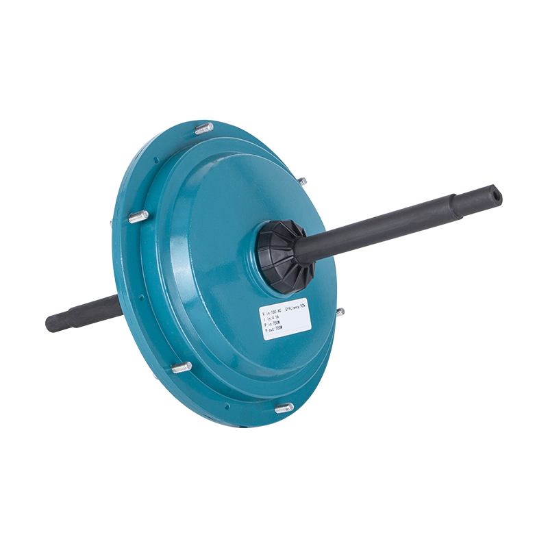
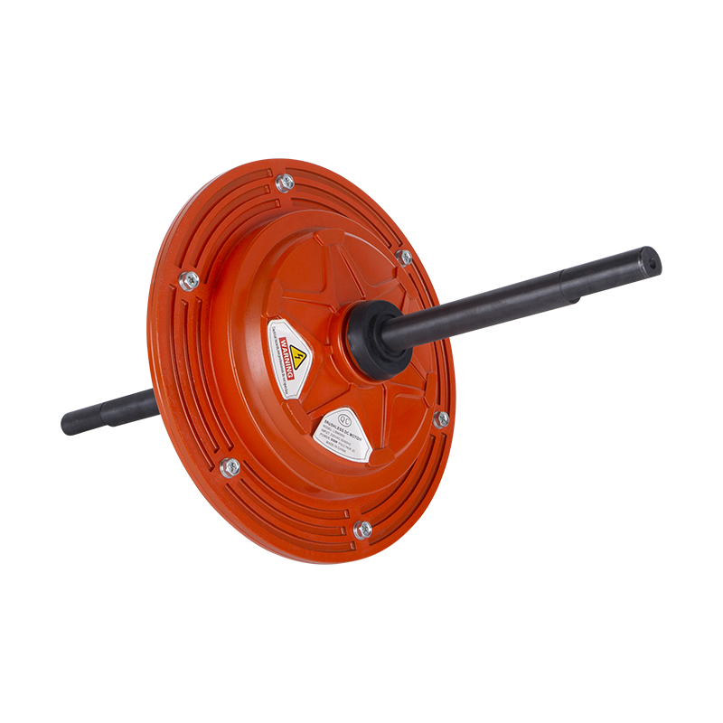
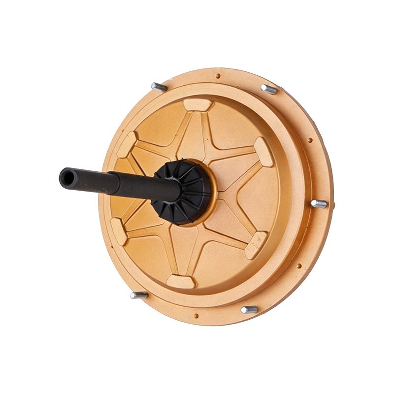 DC149 220V 600W External BLDC Air Cooler MotorLow-power 220V 600W external-rotor BLDC air cooler motor with IP55 and class F insulation, suited to industrial cooling; verify winding constants before ordering.View Product →
The catch is that these are mass-produced units optimised for fan loads, so before ordering, ask for the measured Ke, the line-to-line resistance and the maximum permissible winding temperature, not just the rated power.
Where It Falls Apart: Practical Failure Modes
Most disappointing generator builds fail for reasons that have nothing to do with electromagnetics. The common ones are worth listing because they are all avoidable with a little forethought.
- Overvoltage at high speed. Open-circuit voltage is the highest voltage the machine ever produces. A wind turbine that loses its load in a gust can push the DC link past the capacitor and inverter ratings within seconds.
- No regulation. Output follows both speed and current. Anything needing a stable rail must add a converter, a dump load or a battery with enough capacity.
- Overheating. Continuous current is limited by winding temperature, and generator duty often means a different airflow path from the one the fan cowl was designed for.
- Magnet demagnetisation. Sustained overload at high winding temperature reduces magnet flux, which lowers output permanently.
- Mechanical mismatch. Belt tension and pulley overhang load the front bearing in a direction the original mount never anticipated.
- Wrong rotation expectations. Output phase sequence reverses with direction; a three-phase rectifier does not care, but a synchronous or grid-tied system will.
Higher-power frames behave better thermally because they have more surface area per watt of loss, but they also produce higher voltage at the same speed, which pushes the problem to the electrical side.
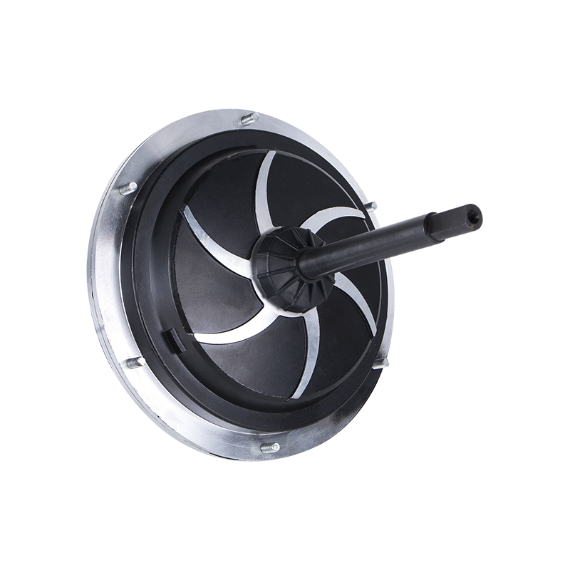
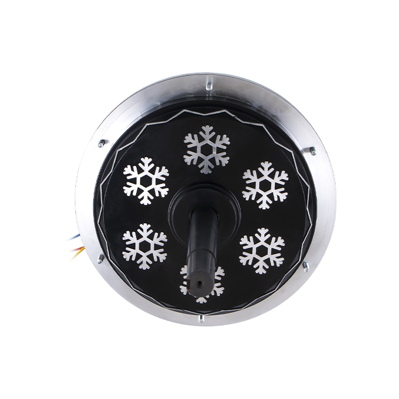 DC198 220V 1500W External BLDC Air Cooler MotorHigh-power 220V 1500W external-rotor BLDC motor for heavy-duty evaporative coolers and large ventilation, with F insulation and optional driver; account for high-speed voltage.View Product →
For any frame above roughly 1 kW, plan on a converter stage with an input voltage rating that covers the open-circuit condition at the highest speed the prime mover can reach, not the nominal operating point.
A Worked Sizing Example
Numbers make the trade-offs concrete. Take a 220 V, 850 W external-rotor BLDC motor with a back-EMF constant of 180 V line-to-line RMS per 1,000 rpm and a line-to-line resistance of about 1.1 ohms. Drive it at 900 rpm with a small engine and belt.
- Open-circuit line-to-line voltage: 0.9 x 180 = 162 V RMS.
- Rectified no-load DC: about 1.35 x 162 = 219 V.
- At 6 A of load current, resistive drop: roughly 7 V, giving about 212 V at the terminals.
- Copper loss in the winding: approximately 3 x (6 / 1.22) squared x 0.55, which is close to 40 W.
The result is a usable 1.27 kW of electrical output at a comfortable speed, except that this exceeds the frame's rating and the winding will not survive it continuously. Cut the current to 3 A and the numbers become roughly 560 W of output with about 10 W of copper loss, which is a sensible continuous point with a healthy margin.
Now change the target. Suppose the load is a 48 V battery instead of a 200 V bus. Reducing speed to 300 rpm gives 54 V line-to-line open circuit, which rectifies to about 73 V, but the sag under 8 A is nearly 9 V and copper loss rises to roughly 70 W. The voltage is now too low and the losses too high for the power wanted, which is the classic signal that the winding is wrong for the job. The correct fix is not more speed but a lower-Ke stator.
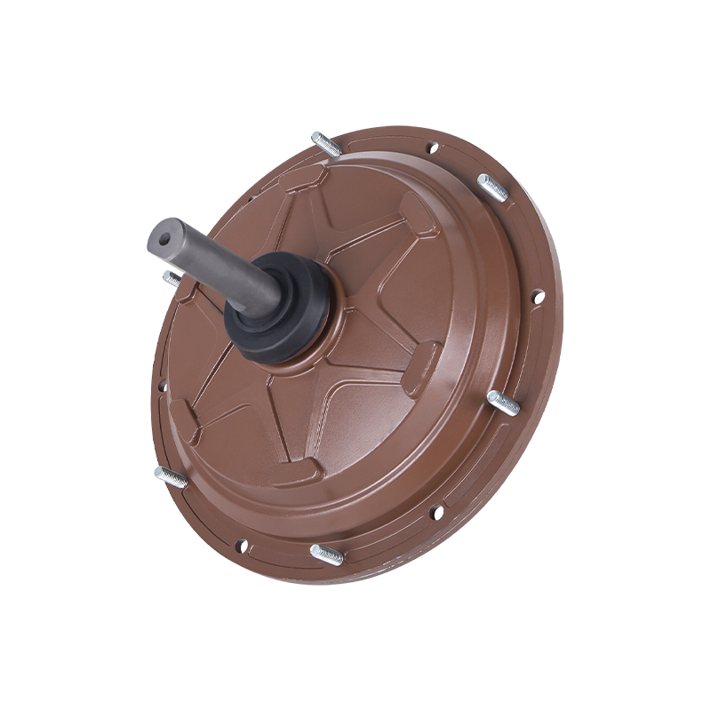
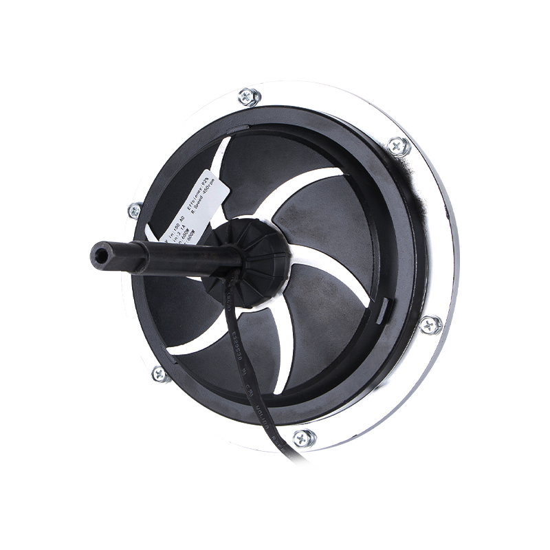 DC149 220V 850W External BLDC Air Cooler Motor850W 220V external-rotor BLDC air cooler motor with direct-drive fan design and IP55 protection; winding variants can address different voltage and loss targets.View Product →
What to Put in an RFQ to a Motor Factory
Because a re-specified winding is usually cheaper than a new machine, the fastest route from concept to hardware is a clear request for quotation. Manufacturers who build BLDC and permanent-magnet motors in volume can typically supply a variant with a different turns count, different wire gauge and a modified shaft or connector without new tooling.
- Target voltage and current at a stated speed, plus the maximum speed the prime mover can reach.
- Required back-EMF constant, or the open-circuit voltage measured at one known rpm.
- Continuous and peak current, with duty cycle and expected ambient temperature.
- Mechanical interface: shaft diameter and length, keyway or flat, mounting flange, direction of rotation.
- Environmental requirements: IP rating, humidity, dust, salt or washdown exposure.
- Whether a Hall sensor set or encoder is needed for control or only for instrumentation.
- Verification data: measured Ke, line-to-line resistance and a no-load voltage test at one speed.
The construction side of the machine matters as much as the winding. Permanent-magnet rotor design, pole count and slot arrangement determine the EMF waveform and the cogging behaviour, and a supplier that builds these machines routinely can explain the trade-offs in plain terms. A useful background read is a guide to BLDC motor construction and permanent-magnet rotors, which helps in framing questions about magnet grade and slot geometry.
Application context matters too. If the generator will sit behind a fan or blower, the same motor families used in industrial fan applications are a sensible starting point, since their speed ranges, mounting patterns and bearing arrangements already match that kind of prime mover and load profile.
The honest summary is that a BLDC motor makes a perfectly serviceable generator as long as the project is designed around its nature rather than against it. It will not regulate its own voltage, it will not tolerate sustained overload, and it will only work well at the speed its winding was chosen for. Get the back-EMF constant right for the prime mover and the load, add a rectifier and a converter stage with adequate voltage headroom, respect the thermal limits of the winding, and the machine behaves predictably for years. Get the winding wrong and no amount of extra electronics will recover the efficiency lost to a mismatched voltage and current operating point.
 Ready To Customise
Your Motor Products?

We are professional motor manufacturers, delivering powerful, stable, and efficient power cores for all industries through precision craftsmanship and innovation.
Contact Us
-
 Mobile:+86 13575536911
-
 Tel:+86 18357538240
-
 Whatsapp:+8618357538240
-
 Email:betty@dbjxmotor.com
-
 Company Address
Copyright © by Shengzhou Jiangxin Motor Technology Co., Ltd. All Rights Reserved.
Wholesale Industrial Fan Motors Manufacturers
