

 English
 русский
 Español
 عربى


No. 8, Duxiu San Road, Ganlin Town, Shengzhou City, Shaoxing City, Zhejiang Province, China

News Category
Product Category
How Does a Hall Effect Sensor Work on a BLDC Motor? The Complete Guide
Content
- 1 The Hall effect: what actually happens in the sensor
- 2 Why a BLDC motor needs rotor position feedback
- 3 Three Hall sensors, six states, six commutation steps
- 4 Latch-type Hall ICs: the component that matters
- 5 Mounting, alignment, and the pole-pair constraint
- 6 Wiring and signal integrity: getting the pulses to the controller
- 7 Hall sensors versus sensorless control: a practical comparison
- 8 What to verify when selecting a Hall-sensored BLDC motor
- 9 Common Hall sensor faults and how to diagnose them
- 10 Why Hall sensors matter in air cooler, fan, and EC motor applications
- 11 Conclusion
Consider a three-phase brushless DC motor that starts to hum, draws excessive current, and refuses to spin. The windings are intact, the controller is powered, and the magnets are fully magnetized. The most common root cause in this situation is not a burned component but a missing signal: the controller does not know where the rotor is.
A brushless DC motor has no mechanical commutator and no brushes. The controller must therefore be told the rotor position before it can energize the correct stator windings at the correct moment. In most fan-type BLDC motors, the component that provides this position information is the Hall effect sensor.
The conclusion in one paragraph is simple. A Hall effect sensor detects the magnetic field of the rotor permanent magnets and converts that field into a digital electrical signal. Three such sensors, placed 120 electrical degrees apart around the stator, produce six binary output combinations that uniquely describe the rotor sector within each electrical cycle. The motor controller decodes these six states and commutes the phase windings in the correct sequence. When the Hall sensors, their wiring, the pull-up circuitry, and the controller commutation logic all work together, the motor spins smoothly from standstill to full speed. When any part of that chain fails, the symptoms are exactly the hum, overcurrent, and vibration described in the opening scenario.
This guide explains, step by step, how Hall effect sensors work on a BLDC motor. We cover the underlying physical effect, the way three sensors generate a six-step commutation sequence, latch-type Hall IC characteristics, sensor placement, wiring, signal integrity, comparison with sensorless control, and practical fault finding. We also look at why Hall-sensored BLDC construction matters for fan, evaporative air cooler, and EC motor applications.
The Hall effect: what actually happens in the sensor
A Hall effect sensor is a semiconductor device that produces an output voltage proportional to the magnetic flux density passing through it. The physics behind it dates back to Edwin Hall in 1879. Hall discovered that when a conductor carrying a current is placed in a magnetic field at right angles to the current direction, the charge carriers are deflected by the Lorentz force. Electrons, or holes in a semiconductor, move to one side of the conductor, so that a measurable transverse voltage appears between the two lateral edges. This voltage is the Hall voltage.
The Hall voltage is proportional to the product of the current and the magnetic field strength, and inversely proportional to the thickness of the conductor and the charge carrier density. In pure conductors such as copper, the carrier density is so high that the Hall voltage is minuscule. This is why practical Hall sensors are made of semiconductor material with a much lower carrier density, arranged in a thin plate called a Hall plate, integrated with a bias current source, a differential amplifier, a comparator, and an output stage in a single IC package.
For commutation of BLDC motors, we do not need to measure the absolute flux density with high resolution. We only need a binary answer to one question: is a north pole or a south pole of the rotor facing the sensor at this moment. Therefore, the output of a commutation-grade Hall sensor is digital. The comparator inside the IC compares the amplified Hall voltage with a reference threshold. When the north pole of the rotor brings the flux density above the operate point (BOP), the output switches to one state. When the south pole later pushes the flux density below the release point (BRP), the output switches back. The difference between BOP and BRP is called hysteresis, and it ensures a clean, chatter-free digital transition as the magnetic field reverses.
Why a BLDC motor needs rotor position feedback
A brushless DC motor is a synchronous permanent-magnet motor. Its stator carries three phase windings, usually connected in star or delta, and its rotor is fitted with alternating north and south permanent magnets. Unlike a brushed DC motor, where the commutator mechanically switches the armature current according to the rotor position, the BLDC motor has no mechanical switching devices. The phase currents must be switched electronically by an inverter, and the switching instants must match the rotor angular position. For the complete treatment of the motor architecture, you can refer to our article about the brushless DC motor working principle.
In a standard three-phase BLDC drive, only two phases are conducting at any one time. The third phase is inactive. The inverter six power switches produce six possible conduction states, which set up a rotating stator field. Torque is produced because the stator field attracts and repels the permanent-magnet rotor and tries to pull the rotor field into alignment. Maximum torque is obtained when the stator field is approximately 90 electrical degrees ahead of the rotor field. To keep that 90-degree relationship as the rotor turns, the controller must switch from one conduction state to the next every 60 electrical degrees. If the switching is early, torque drops; if it is late, torque drops; if the wrong pair is chosen, the motor decelerates instead of accelerating. The important part is that the controller cannot know which pair to choose unless it knows the rotor position. Position feedback is, therefore, not an optional refinement. It is a functional requirement.
There are several ways to obtain rotor position in a BLDC motor. Encoders and resolvers give high resolution, but they are expensive and mechanically complex. Sensorless methods derive position from back-EMF, but they fail at standstill and low speed. For a cost-sensitive fan motor running from a few hundred to a few thousand revolutions per minute, three Hall effect sensors are the industry-standard compromise. They are cheap, robust, and provide absolute rotor position even when the shaft is not moving.
Three Hall sensors, six states, six commutation steps
Hall sensors can be used singly or in multiples. In a three-phase BLDC motor, the standard configuration is three sensors spaced 120 electrical degrees apart around the stator. The sensors are fixed, and the rotor magnets pass by them as the rotor turns. As each sensor is exposed to a north pole, its digital output goes to logic high; when a south pole passes, the output goes to logic low. Since the three sensors are physically separated by 120 electrical degrees, their outputs never change at the same instant. At any given moment, the combination of the three outputs is one of six valid states. Each state corresponds to a rotor sector spanning 60 electrical degrees.
The controller holds a truth table that maps each of the six states to the pair of phases that must be energized in that sector. A representative mapping is shown below.
| Hall state (H1 H2 H3) | Rotor sector | Phases energized |
|---|---|---|
| 101 | 0 to 60 degrees | A+ / B- |
| 100 | 60 to 120 degrees | A+ / C- |
| 110 | 120 to 180 degrees | B+ / C- |
| 010 | 180 to 240 degrees | B+ / A- |
| 011 | 240 to 300 degrees | C+ / A- |
| 001 | 300 to 360 degrees | C+ / B- |
Reading across the table, the sequence of states for one complete electrical cycle is 101, 100, 110, 010, 011, 001. The exact order may be reversed if the motor spins the other way, and the assignment of states to sectors changes if phase wires are swapped; the principle remains identical.
Two points are worth stressing because they explain a number of real-world design decisions. First, any time the Hall combination changes, the controller can immediately switch to the next conduction state. The Hall transition itself can be used as the commutation event. That is why the commutation is often described as Hall-synchronized. Second, because the Hall signals update only once per 60 electrical degrees, the resolution is coarse compared to an encoder. For a motor with several pole pairs, the physical spacing between the sensors becomes correspondingly smaller; we will return to that mechanical constraint in a dedicated section later.
Within each 60-degree sector, the current in the conducting windings is typically regulated by pulse-width modulation (PWM) of the DC bus voltage. The Hall sensors do not regulate current; they only decide which pair of phases receives PWM. The speed is adjusted by changing the PWM duty cycle, while the commutation stepping stays locked to the Hall states. This combination of six-step commutation plus PWM is the basis of virtually all sensored BLDC fan and air-cooler drives.
Latch-type Hall ICs: the component that matters
In a BLDC commutation application, the Hall sensor operates in latching mode; it is usually called a bipolar latch rather than a unipolar switch. A unipolar switch turns on when a field of one polarity exceeds the threshold, and turns off when the field falls back below that threshold. That behavior is fine for detecting the presence of a magnet, but not for commutation. A commutation sensor must remember its state and hold it until the opposite pole arrives. A latch-type Hall IC does exactly this: it latches logic high when it sees a north pole above BOP and does not release until it sees a south pole below BRP. The output then stays high over roughly 180 electrical degrees and low over roughly 180 electrical degrees, producing the evenly balanced square wave that the commutation logic expects.
The key datasheet parameters are not difficult to interpret. The supply voltage of a typical commutation Hall IC is 3.3 to 24 V DC, with an open-drain or push-pull output. Open-drain outputs require an external pull-up resistor; push-pull outputs do not. The switching thresholds BOP and BRP are specified in Gauss or millitesla, and the hysteresis is the difference between them. A typical latch may have an operate point of a few tens of Gauss and a release point of the opposite polarity by a few tens of Gauss; the actual numbers must be matched to the flux density available at the sensor location. The switching frequency must be higher than the maximum electrical frequency of the motor; this is rarely a problem for fan motors but should be checked for high-speed or high-pole-count designs. The ambient temperature range must cover the worst-case location of the sensor inside the motor, including heat soak from the windings. For outdoor equipment such as evaporative air coolers, humidity resistance of the sensor assembly also matters.
One subtle but recurring design issue is the relationship between the Hall sensor placement and the magnet flux in a slotted stator. The sensor does not see only the rotor magnet; it also sees leakage flux from the energized stator windings. If the leakage field is strong enough, it can exceed the BOP and BRP thresholds or shift the commutation timing. Standard remedies are to mask or bracket the sensor, to place it beyond the stator stack, or to temporarily blank the Hall signal during inverter switching by using a short debounce or filter in the controller. This is a typical detail that distinguishes a durable motor design from one with intermittent commutation errors.
Mounting, alignment, and the pole-pair constraint
Mechanical mounting of the Hall sensors is nearly as important as the electrical design. In most small and medium BLDC motors intended for fans, air coolers, and evaporative coolers, the three Hall ICs are soldered to a small printed circuit board mounted on the non-drive end shield of the motor. The rotor carries additional magnets that pass over the sensor board, or the sensor board is positioned so that the main rotor magnets sweep past it, depending on the architecture. The sensor PCB is electrically connected to the controller board by a connector, forming the usual five-wire interface: VCC, GND, and the three sensor outputs.
The electrical spacing of 120 degrees translates into a mechanical angle that depends on the number of magnetic pole pairs. One electrical cycle corresponds to one pole pair, so the mechanical angle between adjacent sensors is 120 electrical degrees divided by the number of pole pairs. For a two-pole motor, the three sensors are spaced 120 mechanical degrees apart. For a four-pole motor, they are spaced 60 mechanical degrees apart. For an eight-pole motor with four pole pairs, the spacing is 30 mechanical degrees. The consequence is that as the pole count rises, the available space for sensor packages shrinks, and the alignment tolerance becomes tighter. This is one reason why many larger fan motors stick to a moderate pole count, and why high-pole-count motors are often designed sensorless or with the sensors mounted directly on the main PCB rather than on a separate board.
Alignment is the second constraint. The sensor board is positioned during assembly so that the switching edge of each Hall output occurs at the correct rotor angle relative to the stator winding of the corresponding phase. If the sensors are misaligned by several electrical degrees in either direction, the commutation event arrives too early or too late, causing current spikes, torque ripple, vibration, and efficiency loss. If the sensors are grossly misaligned, the motor may not start at all. Some designs deliberately introduce a fixed angle between the sensors and the winding axis to create phase advance for high-speed operation, but the offset is then consistent and documented, not accidental.
The external rotor construction used in several air-cooler fan motors puts the stator inside and the rotor cup outside. The obvious advantage for the sensor system is that the Hall board is mounted on the fixed stator side and the magnet ring is on the inside of the rotating cup; the air gap is predictable, and the sensor is protected from the external airflow. For an example of this architecture in a size that faces real airflow duty, the DC149-220V-600W external BLDC air-cooler motor is a representative case.
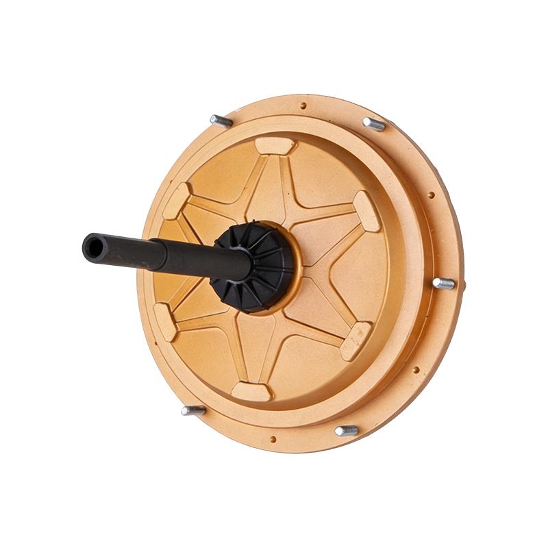 DC149 220V 600W External Rotor BLDC Air Cooler MotorThis 600W external rotor motor is a representative example of stator-mounted Hall sensing, offering predictable air gap and protected sensor placement for reliable commutation in real airflow duty.View Product →
Wiring and signal integrity: getting the pulses to the controller
The Hall outputs are square waves, but they travel through a cable that runs alongside the phase wires carrying rapidly switching PWM currents. Without care, the signal can be corrupted. The most important practical points are:
- Use pull-up resistors of 1k to 10k ohms for open-drain Hall outputs. The value controls both the signal rise time and the immunity. Too low a resistance draws unnecessary current; too high a resistance makes the edge slow and sensitive to capacitance.
- Place a small capacitor near the controller input, typically 1nF to 100nF, to remove high-frequency noise while preserving the commutation edge timing.
- Keep the Hall signal wires twisted or shielded, and separate them from phase conductors wherever the routing allows.
- Connect the sensor ground and the controller ground at a single common point to avoid ground offset. If the sensor is supplied by a separate voltage regulator, make sure the regulator output is stable during PWM transients.
- For long cable runs, differential line drivers or transistor buffers can be inserted, but for motors with up to a few meters of cable, a filtered open-drain signal is usually sufficient.
The commutation logic in the controller usually triggers on the transition edge, not on the level. Any noise that creates an extra transition on a Hall line will cause a premature commutation, which is why debouncing and edge detection are part of the firmware on production controllers. Some inverters blank the Hall inputs for a few microseconds during phase switching, because the rapid voltage change of the switching node capacitively couples into the sensor wires.
One additional protective measure inside the motor is a series resistor in each Hall line near the connector; in combination with the controller-side capacitor, this forms a low-pass filter. If you are sourcing the motor alone, make sure the motor connector pins carry labels for VCC, GND, H1, H2, and H3; an incorrect pinout is the most common field wiring error and can quickly damage the Hall ICs if the supply polarity is reversed.
Hall sensors versus sensorless control: a practical comparison
A recurrent engineering question is whether sensorless back-EMF control can replace Hall sensors. In high-volume applications the answer is sometimes yes, but not without compromises. Sensored control with Hall sensors has one decisive advantage: it works at zero speed. A sensorless drive, by contrast, estimates rotor position from the back-EMF of the open phase, and the back-EMF is proportional to speed. At standstill and at very low rpm, the back-EMF is too small to be measured, so the controller has to apply alignment pulses and open-loop ramping just to get the motor moving. If the load torque is high or changes during startup, the open-loop ramp may fail, stall the motor, or produce momentary reverse rotation.
For air coolers, duct fans, and other propeller loads, the fan itself applies a very low torque at standstill, but the aerodynamic load increases with the square of the speed. A sensored motor starts with full torque from the first Hall transition, which simplifies the controller and guarantees a known direction. A sensorless motor can be made to start if the firmware is well tuned, but the effort then moves into software rather than hardware.
Cost and reliability are usually the main reasons to consider removing sensors. Hall sensors add two or three conductors to the motor cable, a connector, a sensor PCB, and assembly time. On the reliability side, a sensor or solder joint can fail, whereas back-EMF sensing has no additional moving or magnetic part. However, modern Hall ICs are inexpensive and very robust when mounted and protected correctly. For fan motors that run continuously for months, the sensor failure rate is low; the more common failure is mechanical damage to the sensor cable or connector during installation.
| Criterion | Hall sensor control | Sensorless (back-EMF) |
|---|---|---|
| Rotor position at standstill | Available immediately | Not measurable |
| Startup behavior | Deterministic and repeatable | Depends on firmware alignment and ramp |
| Low-speed torque | Full torque from first commutation | Reduced until back-EMF becomes readable |
| Extra components | Three sensors plus PCB and wiring | None |
| Controller complexity | Simple truth table | Estimator, filters, startup state machine |
| Typical fan motor use | Variable speed, quiet low-speed operation | Constant speed, fixed-speed fans |
Ultimately, the choice comes down to the operating envelope. A motor that must produce torque at standstill, hold a fan at low speed, or reverse reliably benefits from Hall sensors. A fixed-speed fan that spins from rest with no load can be sensorless with a carefully tuned startup routine. Most commercial air-cooler motors, EC fan motors, and low-noise BLDC fan motors keep the Hall sensors to guarantee smooth, silent, slow-speed operation and predictable startup.
What to verify when selecting a Hall-sensored BLDC motor
If you are buying a complete motor, you generally do not select the Hall sensor model yourself; the motor manufacturer does. But you should know what to verify, because sensor quality directly affects the start reliability and service life of your equipment.
First, check the sensor supply voltage range against your controller. A motor with Hall sensors powered at 5V cannot run on a 3.3V supply unless the sensors accept 3.3V operation and the pull-ups are connected to the 3.3V rail. Many modern Hall ICs cover 3.3 to 24V. Second, confirm the output logic: open-drain outputs need a pull-up resistor, and the pull-up must be on your controller board. Third, verify the pole-pair count and sensor spacing; this is not configurable by the user. Fourth, consider the environmental rating. If the motor is mounted in the wet air stream of an evaporative cooler or exposed to condensation, the sensor PCB and connector must be protected.
Fifth, check the startup behavior with your actual load. A fan impeller sometimes has a slight resting bias; if the Hall board is misaligned, the motor may occasionally start backwards or vibrate at low speed. The honest test is on the real assembly. Sixth, ask how the motor behaves if a Hall signal is lost. A good controller firmware detects a missing Hall edge, stops generating PWM, and flags a fault rather than continuing with a wrong commutation pattern.
Finally, if you are sizing a motor for a larger cooler, compare the mechanical mounting and shaft configuration. A high-power external rotor motor for big air coolers is a different physical package from a compact EC fan motor. In the higher power class, the DC198-220V-1500W external BLDC air-cooler motor represents the 1500W tier with the same sensored architecture scaled up.
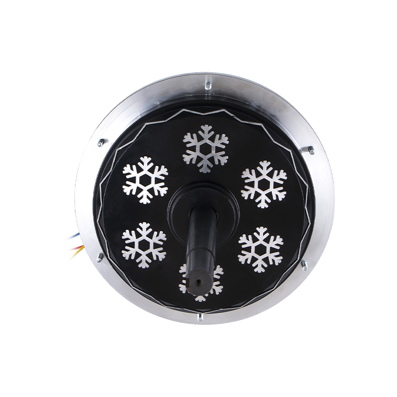 DC198 220V 1500W External Rotor BLDC Air Cooler MotorScaled to the 1500W tier, this high-power external rotor motor shares the same sensored architecture, making it a suitable comparison point when sizing larger coolers with heavier mechanical mounting requirements.View Product →
Common Hall sensor faults and how to diagnose them
Humb, overcurrent, no start, and reverse start appear repeatedly in the field. The following list covers the classic fault modes and where to look first.
- Motor does not start and draws high current: usually the controller never saw a valid Hall state, so it cannot initiate the commutation. Causes include a disconnected sensor, a solder bridge, or a stuck output.
- Motor starts, runs, then stalls when a load is applied: one Hall output occasionally drops out, so the commutated pair becomes wrong. Causes include a poor connection, a cracked solder joint, or an intermittent pull-up contact.
- Motor runs roughly in one direction with excessive vibration: commutation timing is early or late because one sensor is offset, or its threshold is too high to switch exactly at the intended angle.
- Motor rotates backwards intermittently: the state order or startup logic is reversed by a wiring swap of two Hall lines. On some controllers this can be fixed in firmware; otherwise, the sensors are in the wrong physical order.
- Motor runs at a speed lower than commanded with audible ticking: a single Hall output is missing or always high, so the controller forces only a four-state sequence and cannot produce the full six-step torque. This is an easy test: read the three outputs while turning the rotor by hand; they must all toggle exactly once per pole pair.
A useful test procedure is as follows. Disconnect the motor from the inverter, power the Hall board with a bench supply at its rated VCC, connect the three outputs through pull-ups to the logic supply, and rotate the rotor slowly by hand. On an oscilloscope you should see six distinct combinations around the electrical cycle, with clean edges and no double transitions. On a multimeter you can confirm that each output toggles individually, but the oscilloscope reveals the timing relationship between the three channels, which is the part that matters most for commutation.
Also compare the measured sensor spacing in mechanical degrees against the expected value for the pole count: for a four-pole design, the three sensors are 60 mechanical degrees apart, and so on. If one sensor reports logic high continuously even when the opposite magnet pole is directly in front of it, replace that sensor IC. If the output follows the field but the magnetic thresholds are marginal, a magnet with a stronger remanent flux is the usual fix.
Why Hall sensors matter in air cooler, fan, and EC motor applications
The applications in the company product line illustrate the practical relevance. Evaporative air coolers are simple machines, but they represent a demanding motor duty: an impeller load with slow speeds at night, high airflow in the afternoon, mains voltage variations, and a stream of humid air. A sensored external rotor BLDC motor provides the low-speed torque and the guaranteed start direction that the application needs. The external rotor construction keeps the stator and the Hall board protected inside, where condensation and contamination cannot reach the electronics. With PWM control synchronized to the Hall states, the motor can turn the impeller at a fraction of nominal speed without overheating, and it can accelerate quickly to maximum airflow when the control signal demands it.
EC fan motors are the same class of machine; the term EC refers to electronic commutation that replaces mechanical brushing, which is exactly what the Hall-sensored BLDC drive implements. In EC fan motors the Hall sensors determine the rotor sector, the controller applies PWM, and the integrated unit regulates speed and airflow against a setpoint. The advantage of EC fans compared with induction fans is efficiency at partial load. By adjusting the PWM duty cycle and maintaining the commutation through the Hall states, a compact EC fan motor can deliver improved efficiency over a wide operating range. For a 350W-class application on a 220V supply, the ECF35010 EC fan motor is a representative example of this architecture.
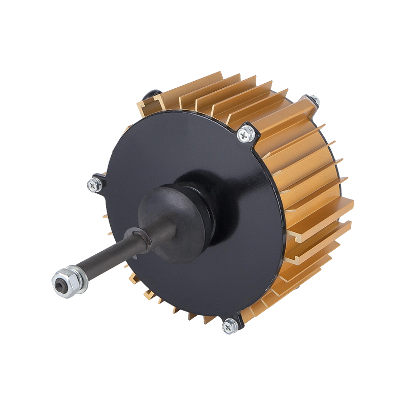 ECF-350-10 220V 350W EC Fan MotorThis 350W EC fan motor exemplifies compact Hall-sensored BLDC commutation, delivering improved partial-load efficiency and quiet operation for ventilation systems in noise-sensitive environments.View Product →
Quiet operation at low speed is another reason the sensored design is preferred in ventilation equipment. Sensorless BLDC drives often have to energize phase pairs for a longer time in the single-step startup phase before the back-EMF is readable, and this produces a hard cut and a clicking noise. Sensored motors commutate at the correct torque angle from the very first transition, so the stator force is constant and quiet. This is why low-noise BLDC motor designs for greenhouses, poultry houses, and residential coolers rely on Hall sensors rather than pure back-EMF estimators.
From the perspective of an equipment builder, the takeaway is practical: a Hall-sensored BLDC motor simplifies controller development, improves startup reliability, and keeps torque steady at low speeds, at the price of a few extra wires. For the air cooler and fan industry, this is almost always an acceptable trade.
Conclusion
The Hall effect sensor is not a mysterious accessory; it is a small latching magnetic switch that tells the controller which sector of the BLDC motor electrical cycle is active. Three sensors at 120 electrical degrees spacing generate six binary codes; the controller maps each code to one of the six conduction steps; and the motor advances from sector to sector with correct torque. The physical effect is simple, and the practical engineering is in the alignment, wiring, thresholds, and filtering.
When you choose a motor for a fan, evaporative cooler, or EC fan, do not treat the Hall sensors as an obscure detail. Their quality and arrangement determine whether the motor starts every time, whether it runs quietly at low speed, and how reliably the controller can switch. Confirm voltage, power class, sensor interface, and environmental protection, and test the startup under your actual impeller load before committing to a design.
 Ready To Customise
Your Motor Products?

We are professional motor manufacturers, delivering powerful, stable, and efficient power cores for all industries through precision craftsmanship and innovation.
Contact Us
-
 Mobile:+86 13575536911
-
 Tel:+86 18357538240
-
 Whatsapp:+8618357538240
-
 Email:betty@dbjxmotor.com
-
 Company Address
Copyright © by Shengzhou Jiangxin Motor Technology Co., Ltd. All Rights Reserved.
Wholesale Industrial Fan Motors Manufacturers
